Electromagnetic induction heat generating roller, heating device, and image forming apparatus
a heat generation roller and induction technology, applied in the direction of electric/magnetic/electromagnetic heating, electrographic process, instruments, etc., can solve the problems of power loss and power loss, and achieve excellent energy efficiency, prevent damage to bearings or the like, and improve heat generation efficiency
- Summary
- Abstract
- Description
- Claims
- Application Information
AI Technical Summary
Benefits of technology
Problems solved by technology
Method used
Image
Examples
embodiment 1
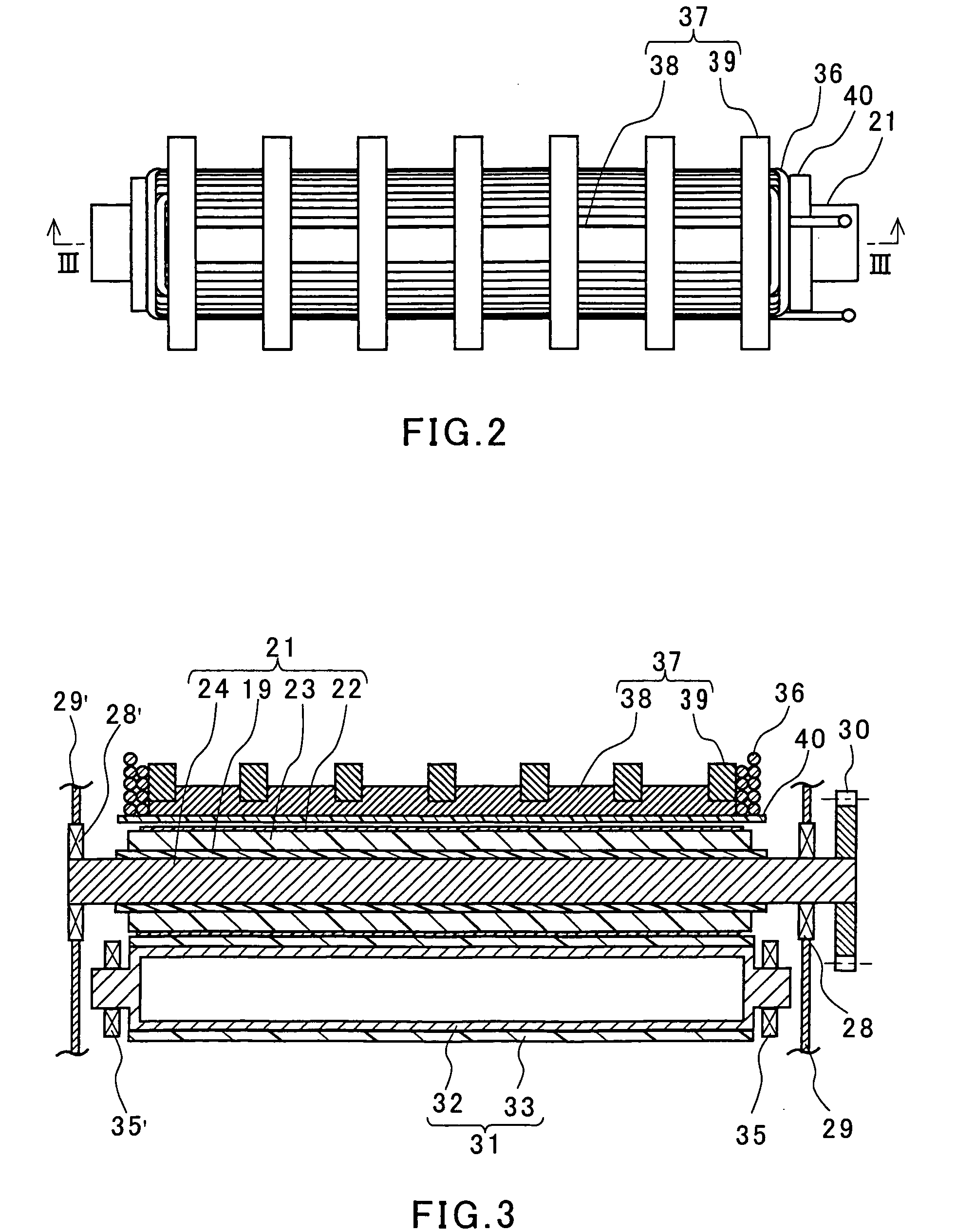
[0053]FIG. 5 is a cross sectional view of an image forming apparatus using a heating device according to an embodiment of the present invention as a fixing device. The heating device according to this embodiment is an electromagnetic induction heating device of the roller heating type. The following description is directed to the configuration and operation of this device.
[0054] Reference numeral 1 denotes an electrophotographic photoreceptor (hereinafter, referred to as a “photosensitive drum”). The photosensitive drum 1, while being driven to rotate at a predetermined peripheral velocity in a direction indicated by an arrow, has its surface charged uniformly to a predetermined potential by a charger 2. Reference numeral 3 denotes a laser beam scanner that outputs a laser beam modulated in accordance with a time-series electric digital pixel signal of image information input from a host device such as an image reading apparatus, a computer or the like, which is not shown in the fi...
embodiment 2
[0083] The only difference between Embodiment 2 and Embodiment 1 lies in the configuration of the electromagnetic induction heat generating roller 21. FIG. 6A is a cross sectional view of an electromagnetic induction heat generating roller according to Embodiment 2 of the present invention that is used in the image forming apparatus shown in FIG. 5. FIG. 6B is an expanded sectional view of a portion 6B shown in FIG. 6A. In FIGS. 6A and 6B, like reference characters indicate like members that have the same functions as those described with regard to Embodiment 1, for which detailed descriptions are omitted.
[0084] A heat generating roller 21 according to this embodiment includes a core material 24, an elastic layer 23, a heat generating layer 22, a second elastic layer 26, and a mold releasing layer 27, which are provided outwardly in this order. As in the case of Embodiment 1, the core material 24 is formed of a non-magnetic stainless material. Unlike the case of Embodiment 1, the h...
embodiment 3
[0087] The only difference between Embodiment 3 and Embodiment 1 lies in the configuration of the magnetism shielding layer of the electromagnetic induction heat generating roller 21. FIG. 7A is a schematic perspective view of a core material 24 of an electromagnetic induction heat generating roller according to Embodiment 3 of the present invention. The core material 24 includes a magnetism shielding layer.
[0088] In this embodiment, the magnetism shielding layer is formed by using a ring (hollow cylindrical member) 51 shown in FIG. 7B and is composed of a plurality of the rings 51. The plurality of the rings 51 are fitted externally around the core material 24 and fixed thereto. The ring 51 contains a magnetic material such as ferrite. It is preferable that the adjacent rings 51 are joined to each other. However, the adjacent rings 51 also may be spaced slightly from each other.
[0089] In place of the ring 51, an arc-shaped member 52 shown in FIG. 7C may be attached to an outer su...
PUM
 Abstract
Description
Claims
Application Information
 - R&D
- Intellectual Property
- Life Sciences
- Materials
- Tech Scout
- Unparalleled Data Quality
- Higher Quality Content
- 60% Fewer Hallucinations
Browse by: Latest US Patents, China's latest patents, Technical Efficacy Thesaurus, Application Domain, Technology Topic, Popular Technical Reports.
© 2025 PatSnap. All rights reserved.Legal|Privacy policy|Modern Slavery Act Transparency Statement|Sitemap|About US| Contact US: help@patsnap.com


