
Soap dispenser system and valve arrangement therefor

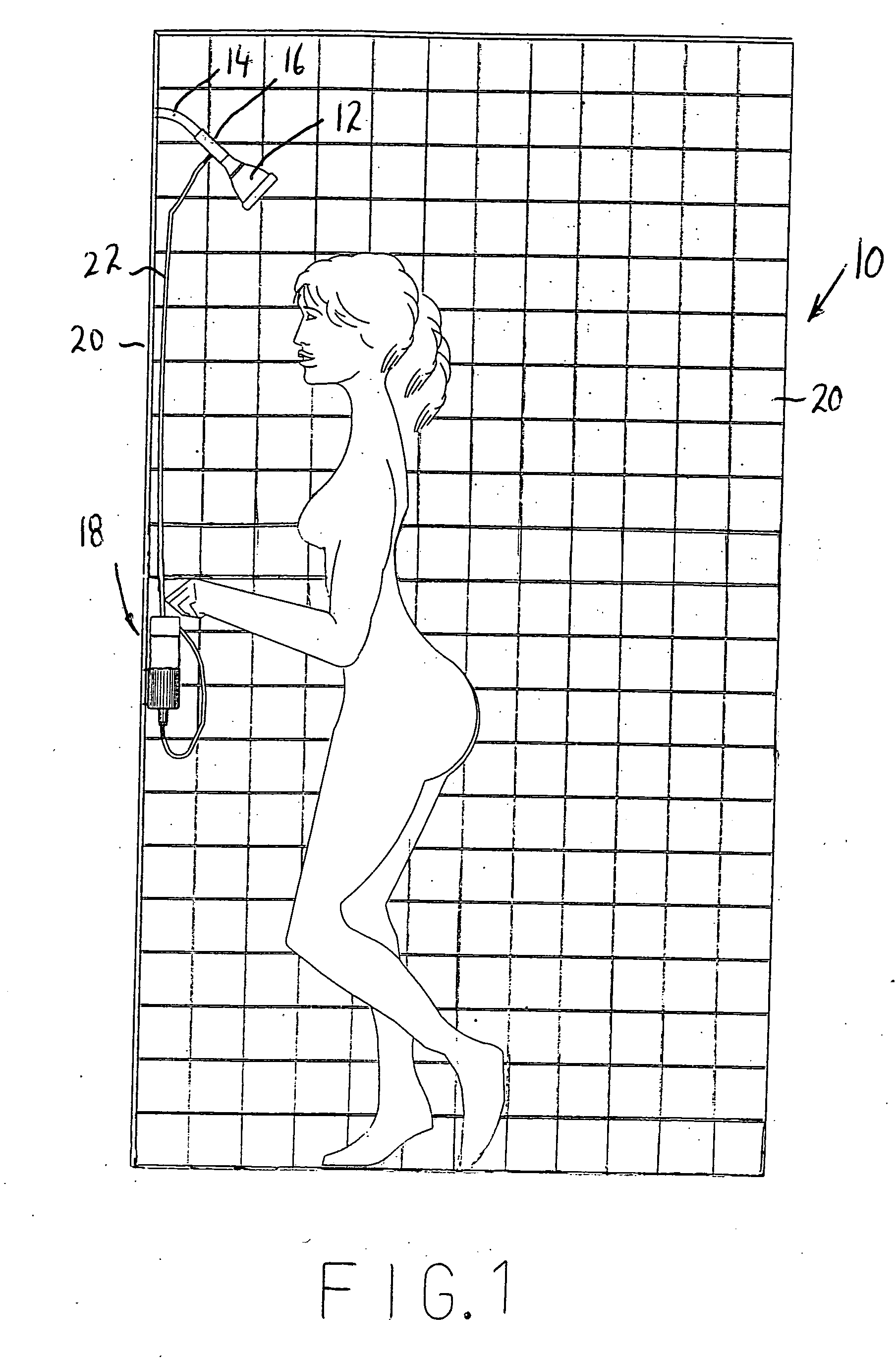
a dispenser and valve arrangement technology, applied in the field of soap dispensers, can solve the problems of insufficient valve arrangement of conventional pump dispenser bottles and conventional pump dispenser bottles for delivering metered doses of soap, and the difficulty of using bar soap and conventional pump dispenser bottles by invalids with limited mobility and strength, etc., to achieve convenient activation, easy and economical use and manufacture

Inactive Publication Date: 2005-07-14
LEONARD BRIAN T +1
View PDF13 Cites 12 Cited by
  • Summary
  • Abstract
  • Description
  • Claims
  • Application Information

AI Technical Summary

Benefits of technology

[0006] It is yet another object of the present invention to provide a soap dispenser system and valve arrangement therefor in which the soap dispenser is easily activated by an invalid or any other person pressing down on the top of the soap dispenser.
[0007] It is a further object of the present invention to provide a soap dispenser system and valve arrangement therefor that is easy and economical to use and manufacture.
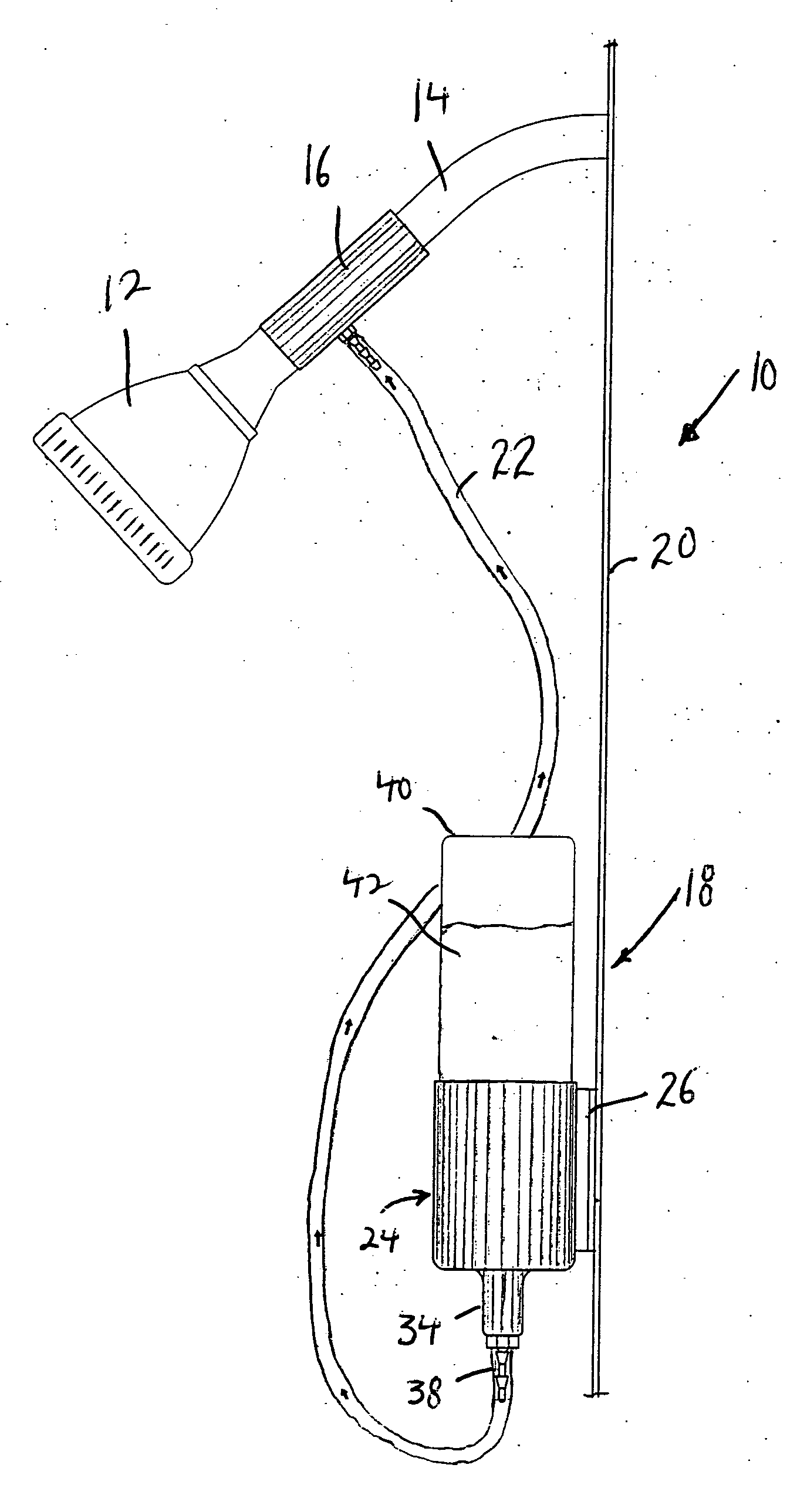
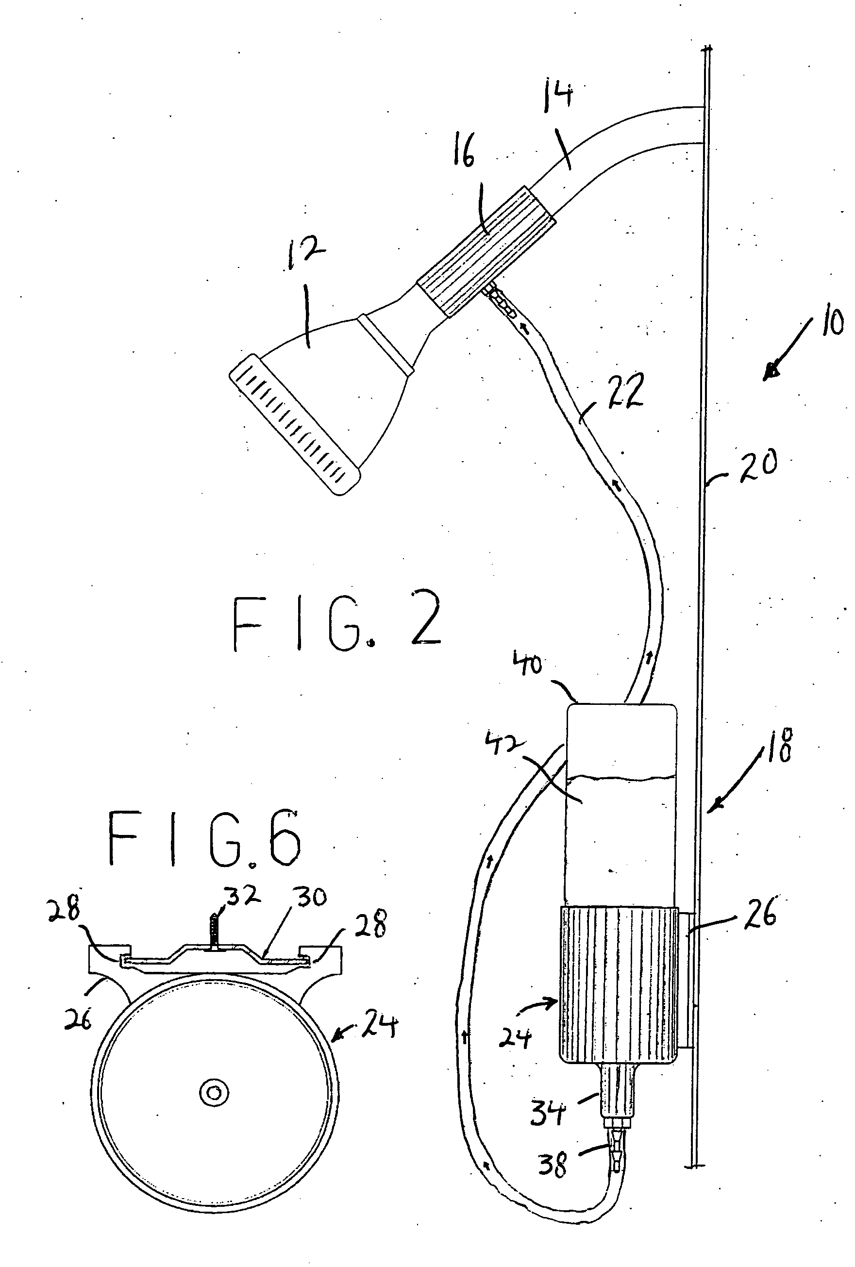
[0008] In accordance with an aspect of the present invention, a soap dispenser system comprises a suction tube including a main through bore for supplying water from a water line pipe to a shower head, and a soap supply bore intersecting the main through bore; a soap dispenser positioned remote from the suction tube for controlling dispensing of soap from a container having soap therein; and a supply tube connecting the soap dispenser to the soap supply bore of the suction tube in order to provide soap from the soap dispenser to the suction tube by means of suction created by the water traveling through the main through bore of the suction tube; the soap dispenser including an inner tube having an inlet and an outlet fluidly connected with the supply tube, an outer tube movably mounted over the inner tube and connected with the container, the outer tube having an inlet adapted to be fluidly connected with soap from the container and an outlet adapted to be fluidly connected with the inlet of the inner tube, a biasing device for applying pressure between the inner tube and the outer tube in a direction to move the inner tube and outer tube apart, a valve for permitting soap to enter the inlet of the inner tube when the outer tube is moved toward the inner tube against the force of the biasing device and which prevents soap from entering the inlet of the inner tube when the outer tube is moved away from the inner tube by the biasing device.
[0013] In another embodiment, the valve of the soap dispenser includes a first biased seal for permitting soap to travel through the inner tube when a release force is applied to the container and for preventing soap to travel through the inner tube when a the release force is not applied to the container, a second biased seal for preventing soap from escaping from the container through the outer tube when the release force is applied to the container and for permitting soap to escape from the container through the outer tube when the release force is not applied to the container, and a chamber between the first and second biased seals for accumulating a metered dosage of soap for supply to the supply tube, such that the chamber is loaded with the metered dosage of soap when the release force is not applied to the container, and the metered dosage of soap is supplied through the inner tube when the release force is applied to the container.

Problems solved by technology

However, the use of bar soap and conventional pump dispenser bottles can be difficult by invalids who have limited mobility and strength.
Further, the valve arrangements used in the conventional pump dispenser bottles and the wall mounted soap dispensers are not entirely adequate for delivering metered doses of soap.

Method used


Image

  • Soap dispenser system and valve arrangement therefor
  • Soap dispenser system and valve arrangement therefor
  • Soap dispenser system and valve arrangement therefor

Examples


first embodiment

[0058] By providing a raised up post 134 extending within cup 124 and openings 124e in bottom wall 124b, bottle 140 sits above the upper surface of bottom wall 124b of cup 124. This allows water that enters between cup 124 and bottle 140 to drain out, and also provides for air to enter in through openings 124e and enter through bore 134c which has a sloppy or loose fit with inner tube 162 of valve arrangement 148. It has been found that the additional air entering into through bore 134c from openings 124e provides for more aeration of the water, resulting in a greater lather of the soap exiting shower head 12. Specifically, with soap dispenser system 10 according to FIGS. 1-9, the lather of the soap was not as great as compared with soap dispenser system 110 of the embodiment of FIGS. 10-16.

[0059] Further, unlike conventional devices which require an on / off knob or button and in which any suction is lost when the knob is turned to the off position, there is always a constant suction...

second embodiment

[0071] This has the advantage that the second embodiment can operate to dispense a metered dosage of soap, or a continuous supply of soap. Specifically, if bottle 140 is depressed down and immediately let up, a small metered dose of soap will enter opening 175 for dispensing with the water from the shower head. On the other hand, if bottle 140 is depressed down and a continuous pressure is applied thereto, opening 175 remains open, so that the soap within outer tube 150 will continuously drain, and additional soap from bottle 140 that enters outer tube 150 after ball 195 falls down, will also drain through opening 175, until the external pressure on bottle 140 is released.

[0072] Once the external pressure on bottle 140 is released, spring 193 again forces bottle 140 upwardly. This carries valve 185 therewith until the upper edge of inner circumferential wall 189 abuts against the underside of annular stop 171, thereby once again closing off opening 175.

[0073] Of course, it will be ...


PUM


Abstract

A soap dispenser system includes a venturi suction tube having a soap supply bore intersecting the main through bore; a soap dispenser controlling dispensing of soap from a container; and a supply tube connecting the soap dispenser to the soap supply bore of the suction tube; the soap dispenser including an inner tube having fluidly connected with the supply tube, an outer tube movably mounted over the inner tube and connected with the container, the outer tube fluidly connected with soap from the container and adapted to be fluidly connected with the inlet of the inner tube, a spring applying pressure between the inner tube and the outer tube in a direction to move them apart, a valve permitting soap to enter the inlet of the inner tube only when the outer tube is moved toward the inner tube against the force of the biasing device.

Description

BACKGROUND OF THE INVENTION [0001] The present invention relates generally to soap dispensers, and more particularly, is directed to a soap dispenser system particularly suitable for invalids and a valve arrangement therefor. [0002] Most people use bar soap or liquid soap from a conventional squeeze bottle when taking a shower. Alternatively, it is known to provide a wall mounted soap dispenser in a shower with a push button at the bottom or side of the dispenser. However, the use of bar soap and conventional pump dispenser bottles can be difficult by invalids who have limited mobility and strength. Further, the valve arrangements used in the conventional pump dispenser bottles and the wall mounted soap dispensers are not entirely adequate for delivering metered doses of soap. Lastly, such arrangements are separate and apart from the water delivery in the shower. OBJECTS AND SUMMARY OF THE INVENTION [0003] Accordingly, it is an object of the present invention to provide a soap dispe...

Claims


Application Information

Patent Timeline
Patent Type & Authority Applications(United States)
IPC IPC(8): E03C1/046
CPCY10S137/903E03C1/046Y10T137/0335Y10T137/87627
Inventor LEONARD, BRIAN T.HARTMANN, THOMAS C.
Owner LEONARD BRIAN T
Learn More