
Ethernet to frame relay interworking with multiple quality of service levels

a technology of ethernet and frame relay, which is applied in the direction of data switching networks, instruments, digital transmission, etc., can solve the problems of fr standards not supporting multiple qos levels per connection, and the types of connectivity create many challenges

Active Publication Date: 2005-06-30
TELEFON AB LM ERICSSON (PUBL)
View PDF13 Cites 46 Cited by
  • Summary
  • Abstract
  • Description
  • Claims
  • Application Information

AI Technical Summary

Benefits of technology

[0018] The present inventions support multiple QoS, while maintaining operations simplicity, bandwidth sharing, segregation among traffic classes, scalability, and support of tagged and untagged interfaces.

Problems solved by technology

This demand for various types of connectivity creates many challenges.
A primary challenge is mapping the data correctly from one type of technology to another without traffic loss or data-integrity problems.
Another challenge involves meeting service guarantees to the customer to meet the applications' requirements.
Similarly FR Standards do not support multiple QoS levels per connection.

Method used


Image

  • Ethernet to frame relay interworking with multiple quality of service levels
  • Ethernet to frame relay interworking with multiple quality of service levels
  • Ethernet to frame relay interworking with multiple quality of service levels

Examples


second embodiment

[0069]FIG. 3 illustrates a schematic of an Ethernet / FR communication system 50 according to the present invention. The communication system 50 includes a first CE 52 connected to first IWU 54 with multiple Ethernet port connections (60, 62, 64, 66). The communication system 50 further includes a second CE 58 connected to a second IWU 56 with multiple data link connections (70, 72, 74, 76). The IWUs 54, 56 are also connected together over a network link (not shown) through a core network 61.

[0070] In this embodiment of the invention, the data packets transmitted across the network from the first CE 52 to the second CE 58 are each classified with a QoS level as described above. Ethernet data packets are transmitted from the first CE 52 to the first IWU 54 over the multiple Ethernet port connections, with each port connection transmitting data packets designated with a specific QoS level. For example, the Ethernet port 60 may be used to transmit platinum level data packets, the Etherne...

third embodiment

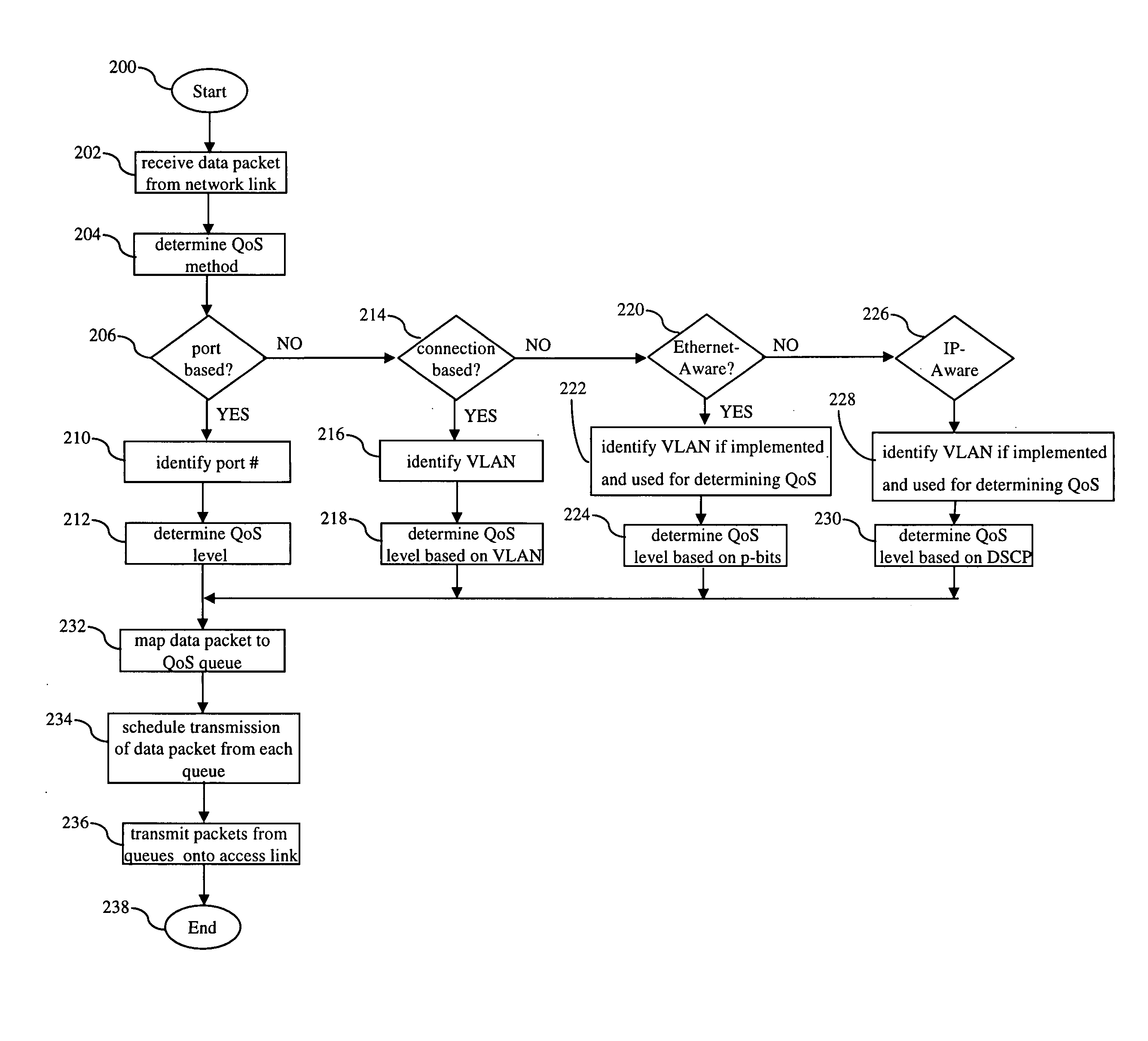
[0076] In particular, FIG. 4 is a schematic of the present invention including a single Ethernet interface and multiple FR DLCs where multiple QoS levels are provided. In such an embodiment, the FR side uses one DLC for each QoS and the Ethernet side uses one interface (in VLAN-unaware mode) or one VLAN for all QoS levels. The p-bits are used for determining QoS. This configuration results in segregation of each QoS stream on the FR side for interoperability with legacy FR equipment, while using a single port or VLAN on the Ethernet side for efficiency and scalability.

fourth embodiment

[0077]FIG. 5 is a schematic of the present invention including a single Ethernet interface (or VLAN) and a single FR DLC where multiple QoS levels are provided. In such an embodiment, one DLC with Diff-Serv DSCP (or any other L3-L7 protocol, which may also include policy attributes, e.g., subscriber-ID) selects QoS on the FR side while one Ethernet interface or one VLAN with Diff-Serv DSCP (or any other L3-L7 protocol together with policy attributes) selects QoS on the Ethernet side. This configuration results in operational simplicity, scalability, and dynamic bandwidth sharing and can work with either Ethernet interfaces operating in VLAN-unaware or VLAN-aware mode. However, this configuration is not a pure L2 service, but depends on L3 or higher layer protocol and may not be suitable for non-IP traffic thereby requiring modern IP-Aware Ethernet and FR switches. The FIG. 5 configuration is similar to that of FIG. 2, except that Upper Layer Protocol (ULP) information (such as IP Di...


PUM


Abstract

A method of supporting multiple quality of service (QoS) levels for data being transmitted between two networking devices, such as customer equipment (CE), that use Ethernet and Frame Relay (FR). The method supports multiple QoS services in a network where a first CE is connected to a first edge device (interworking unit) using the Ethernet protocol and a second CE is connected to a second edge device using the FR protocol. The edge devices may be directly connected together or they may be connected through a network backbone using any generally accepted network protocol. The first CE may be connected to the first edge device using a single Ethernet port, multiple Ethernet ports, a single virtual local area network (VLAN), or multiple VLAN's. The second CE is connected to an edge device using a single data link connection (DLC), or multiple DLC's. The method ensures QoS for data transmitted between the first and the second CE via the Ethernet protocol to the FR protocol and vice versa.

Description

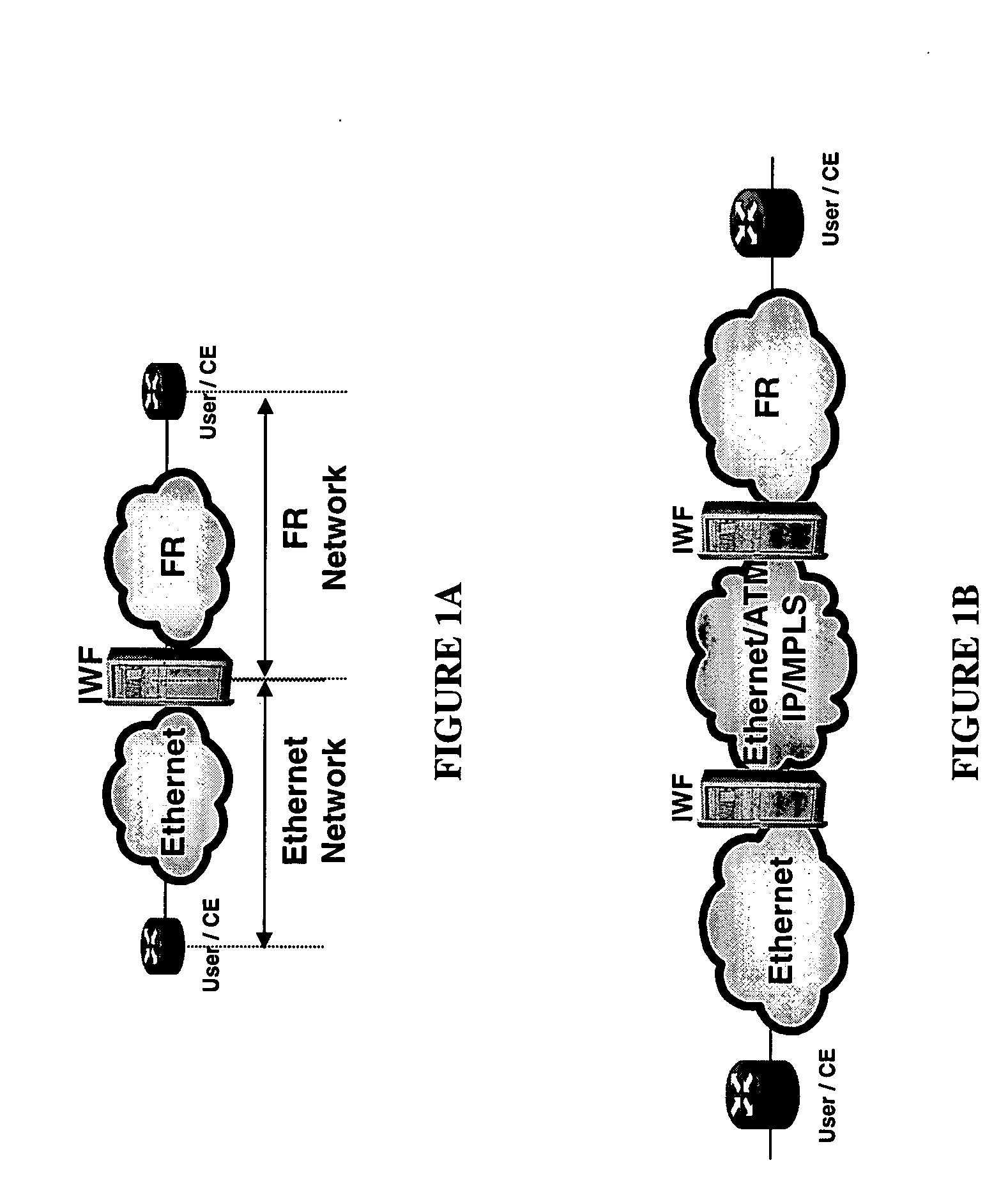
FIELD OF THE INVENTION [0001] The present invention relates to methods of supporting multiple quality of service (QoS) levels for packets being transmitted over Ethernet and Frame Relay (FR) networks. BACKGROUND OF THE INVENTION [0002] Service providers are committed to providing the type of connectivity their customers require. As a result, the presence of Frame Relay (FR), Asynchronous Transfer Mode (ATM), or Point-to-Point (PPP) technologies on the customer side of the network is not uncommon. These feeds usually connect to a multi-service switch / router. [0003] Ethernet is increasingly being used to interconnect customer equipment through provider networks. The high-speed uplink, however, is often ATM, Packet over Synchronous Optical Network (POS), or Gigabit Ethernet. This demand for various types of connectivity creates many challenges. A primary challenge is mapping the data correctly from one type of technology to another without traffic loss or data-integrity problems. Anoth...

Claims


Application Information

Patent Timeline
Patent Type & Authority Applications(United States)
IPC IPC(8): G06F15/16H04L12/46
CPCH04L12/4641
Inventor RABIE, SAMEHPOMMAINVILLE, RICHARDWHATMAN, JOHNABDULLAH, BASHARDAVIES, JOHN ROSSERBARKA, BAGHDAD
Owner TELEFON AB LM ERICSSON (PUBL)
Learn More