
Anastomosis device, tools and methods of using

a technology of anastomosis and anastomosis chamber, which is applied in the field of surgery, can solve the problems of introducing a risk of dislodging plaque that may have accumulated, stroke or other serious medical complications, and mechanical damage to the blood cells,

Inactive Publication Date: 2005-06-30
MAQUET CARDIOVASCULAR LLC
View PDF99 Cites 63 Cited by
  • Summary
  • Abstract
  • Description
  • Claims
  • Application Information

AI Technical Summary

Benefits of technology

[0020] A device holder for securing an anastomosis device for loading a graft thereon is provided. The device holder includes a first portion dimensioned to receive a base portion of the anastomosis device, and a second portion adapted to interact with the first portion to apply a clamping force for retaining the anastomosis device between the first and second portions, so that the device holder securely holds the anastomosis device without applying any hoop stress to the anastomosis device.
[0029] A graft loader for facilitating the loading of a graft on an anastomosis device having already been captured on a deployment tool is disclosed, wherein the graft loader includes a main body having first and second portions configured to split apart. The graft loader is configured to be mounted over a distal end of the deployment device over the anastomosis device, and each portion includes at least one slot for receiving and holding a long thin member having been threaded through the tube and loader. The hook end of each long thin member is pierced through a wall of the graft to be loaded prior to threading the long thin members through the deployment tool and graft loader. After threading the long thin members through the deployment tool and graft loader, the long thin members can be pulled distally to draw the graft into the longitudinal slot of the deployment tool and through the loader.
[0031] The first and second portions of the loader may each be provided with a handle extending therefrom for facilitating splitting of the main body.
[0037] Further provided are additional tools for loading and / or everting a vessel with respect to an anastomosis device. One example of an eversion tool includes a proximal end portion adapted to guide the eversion tool into a distal end of the vessel to be everted, and an expandable member positioned between the proximal end portion and a main body portion of the tool. The expandable member is capable of assuming a first outside diameter, in its relatively unbiased or non-expanded state, which is of a size that permits it to be slid into the open end of the vessel. Upon compressing the expandable member between the proximal end portion and the main body portion, the expandable member assumes a second outside diameter greater than the first outside diameter, which is sufficient to expand the vessel, facilitating the ease with which the vessel end may be flipped over to evert it.
[0041] The proximal portion includes an anchor configured to wedge the vessel against an inner surface of the anastomosis device to prevent backsliding of the vessel with respect to the anastomosis device during performance of the eversion.

Problems solved by technology

Recently, it has been found that the clamping of the aorta introduces a risk of dislodging plaque that may have accumulated on the internal wall of the aorta in the vicinity of the clamping.
Dislodgment of plaque can cause emboli in various locations in the patient's body, cutting off the blood supply downstream of the locus of the embolus, which can cause a stroke or other serious medical complications.
Further, the heart-lung bypass machine can cause mechanical damage to the blood cells which furthers the risk of medical complications, due to potential clot formation.
While beating heart procedures reduce the associated risks of stroke and other post-operative complications associated with the clamping of the aorta and the use of the heart-lung bypass machine, they also increase the difficulty in performing what were already difficult and delicate anastomosis procedures that must be performed to connect the bypass graft or grafts during the CABG procedure.
Manual suturing is difficult, time-consuming and requires a great deal of skill and manual dexterity on the part of the surgeon performing the anastomosis.
The difficulties presented in performing anastomoses by manual suturing are only magnified when they are done during a beating heart CABG procedure as the beating of the heart introduces perturbations that make it even more difficult to throw the sutures in a reliable and consistent manner.

Method used


Image

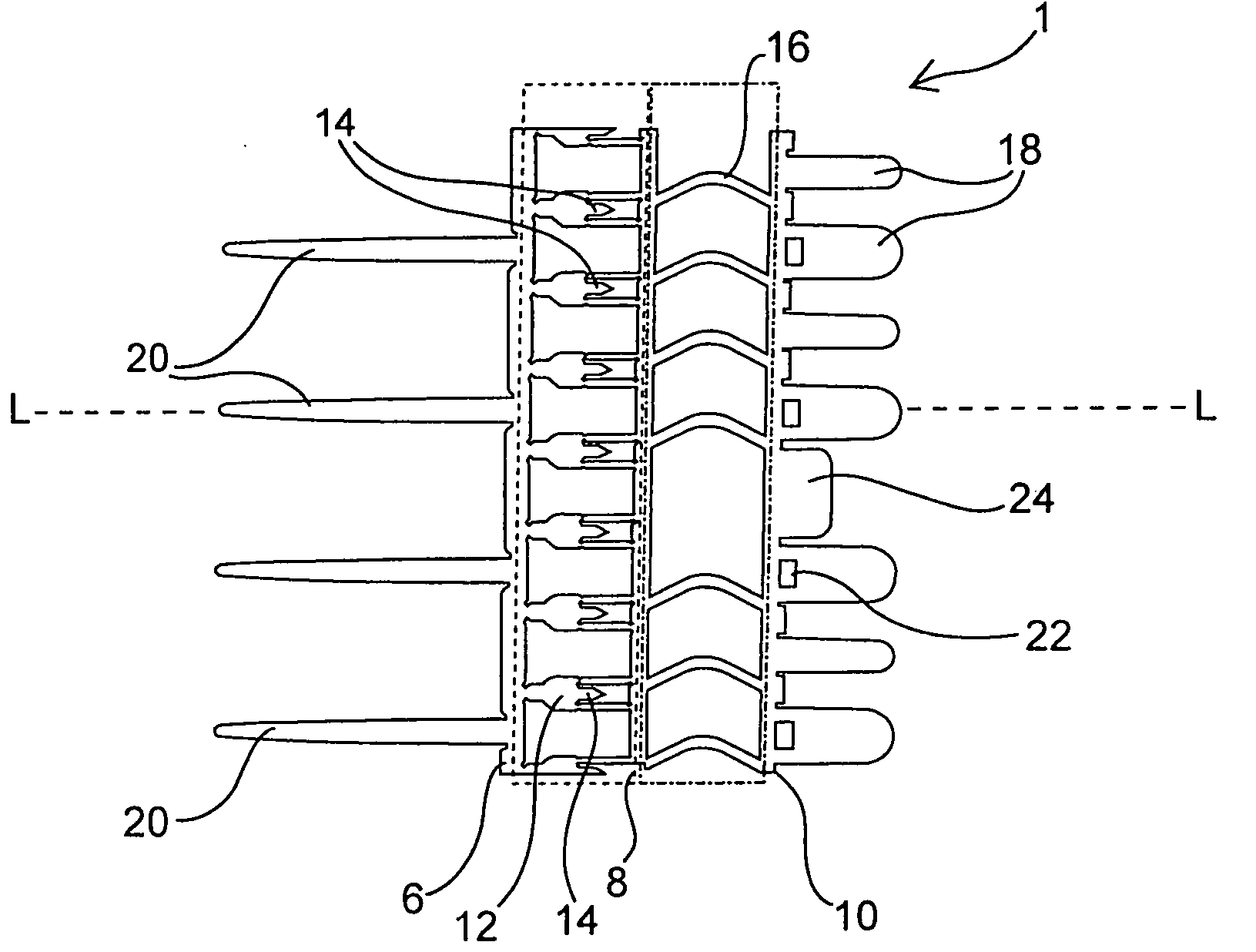
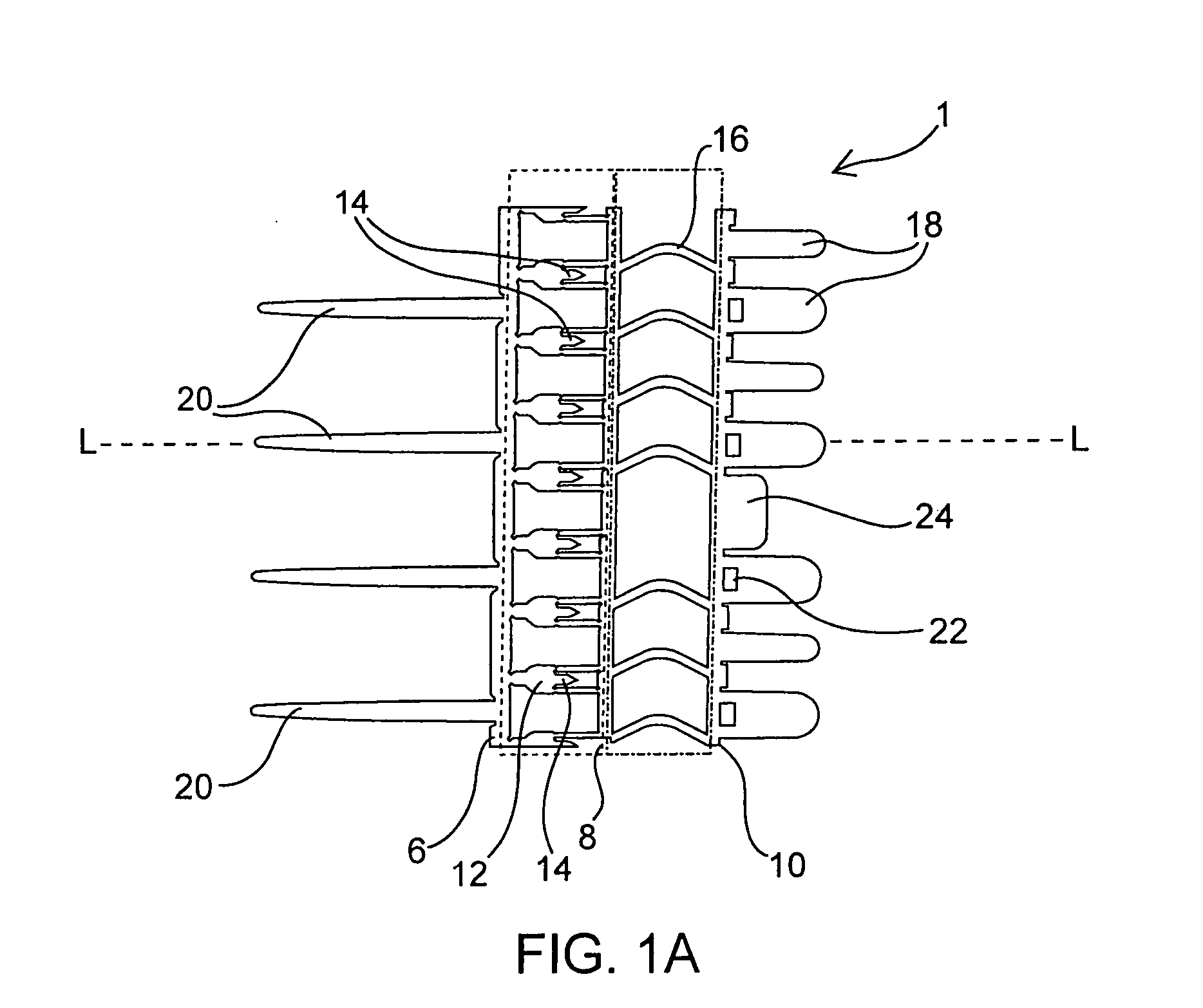
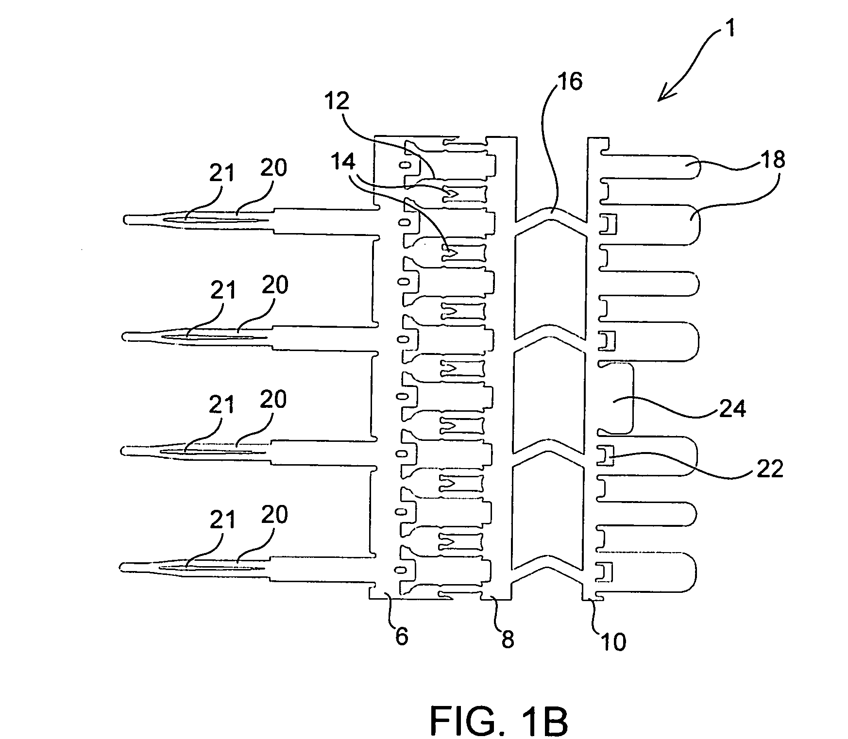
  • Anastomosis device, tools and methods of using
  • Anastomosis device, tools and methods of using
  • Anastomosis device, tools and methods of using

Examples


Embodiment Construction

[0126] Before the present devices, tools and methods are described, it is to be understood that this invention is not limited to a particular device, method step, or tool described, as such may, of course, vary. It is also to be understood that the terminology used herein is for the purpose of describing particular embodiments only, and is not intended to be limiting, since the scope of the present invention will be limited only by the appended claims.

[0127] Where a range of values is provided, it is understood that each intervening value, to the tenth of the unit of the lower limit unless the context clearly dictates otherwise, between the upper and lower limits of that range is also specifically disclosed. Each smaller range between any stated value or intervening value in a stated range and any other stated or intervening value in that stated range is encompassed within the invention. The upper and lower limits of these smaller ranges may independently be included or excluded in...


PUM


Abstract

Anastomosis devices, tools and methods of performing sutureless anastomosis. Anastomosis devices are provided for fixing a first conduit to a second conduit in an anastomosis, where the conduits are joined by interfacing their inner walls together. The conduit which is loaded on the anastomosis device may be mounted in such a way that the internal wall of the conduit does not make contact with the anastomosis device.

Description

CROSS-REFERENCE [0001] This application is a continuation-in-part application of co-pending application Ser. No. 10 / 746,966 filed Dec. 24, 2003, and titled “Anastomosis Device, Tools and Method of Using”, which is incorporated herein by reference in its entirety and to which application we claim priority under 35 USC §120.FIELD OF THE INVENTION [0002] The present invention relates to the field of surgery. More particularly, the present invention relates to devices, tools and methods for performing sutureless anastomoses. BACKGROUND OF THE INVENTION [0003] There are many medical procedures which require the performance of one or more anastomoses in which a conduit such as a vessel, duct, graft or other tubular structure must be joined to another vessel, duct, or other hollow structure such as an organ to establish continuity between these structures. One of the more prevalent needs for improving anastomosis techniques lies with the treatment of coronary artery disease, where a stenos...

Claims


Application Information

Patent Timeline
IPC IPC(8): A61B17/064A61B17/08A61B17/10A61B17/11
CPCA61B17/0644A61B17/11A61B2017/1135A61B2017/1107A61B17/1114
Inventor ABBOTT, RYANLIU, GREG C.
Owner MAQUET CARDIOVASCULAR LLC
Learn More