Interchangeable wire drive for wire feeder and spool gun

Inactive Publication Date: 2006-09-21
LINCOLN GLOBAL INC
View PDF15 Cites 51 Cited by
  • Summary
  • Abstract
  • Description
  • Claims
  • Application Information

AI Technical Summary

Benefits of technology

[0007] The present invention is directed to an interchangeable and / or modular welding wire feed drive for welding wire used in a welding system such as, but not limited to, an electric arc welding system. In accordance with one aspect of the present invention, the welding wire feed drive is designed to be a modular-detachable unit. The welding wire feed drive system can be designed to be a) detachably connected to a wire feeder that is integrated in a welding unit, b) detachably connected to a separate wire feeder that is used in conjunction with a welding unit, and / or c) detachably connected to a wire feeder that is on or integrated with a welding gun. As can be appreciated, the welding wire feed drive can be designed to be detachably connected in other and / or additional ways and / or regions of a welding system. The welding wire feed drive is a versatile system that enables a user to configure the wire feeding arrangement of a welding system for a particular operation. When the welding system is to be used with a more rigid welding wire (e.g., carbon steel based wire, stainless steel based wire, titanium wire, nickel based wire, etc.), the welding wire feed drive is typically placed in a wire feeder system that is integrated in and / or is used in conjunction with a welding unit. In this configuration, the welding wire feed drive draws welding wire from a wire source and then pushes the welding wire through a welding cable that is connected to a welding gun and then through the welding gun to be deposited in molten form on a workpiece. When the welding system is to be used with a less rigid welding wire (e.g., aluminum based wire, etc.), the welding wire feed drive is typically placed in a wire feeder system that is on or integrated with a welding gun. In this configuration, the welding wire feed drive draws the welding wire from a wire source and then pushes the welding wire through the welding gun to be deposited in molten form on a workpiece. As can be appreciated, a more rigid welding wire can also be used in a spool gun, but such a setup is typically not used due to the disadvantages associated with the bulkiness and additional weight of a spool gun. The ability to use the welding wire feed drive in both types of welding operations reduces the amount of equipment an operator needs for various types of welding operations, simplifies the setup ofthe welding system when converting between a welding operation that uses a more rigid welding wire and a less rigid welding wire, and / or reduces the equipment cost associated with equipping the welding system for use in a variety of different welding operations.
[0008] In accordance with another and / or alternative aspect of the present invention, the welding wire feed drive includes a drive housing designed to be detachably connectable to the welding wire feed system. The drive housing is typically formed of a durable material (e.g., metal, plastic, reinforced polymers, etc.) so as to withstand the typical environment of a welding system and / or to protect one or more components contained within the drive housing. The drive housing is configured so that it can be both connected to a drive housing interface on 1) a stand-alone wire feeder and / or a wire feeder integrated in a welder unit and 2) a welding gun and / or wire feeder system integrated with a welding gun. In one specific design, the drive housing interface of a welding gun may merely constitute a welding gun handle that is connectable to the drive housing; however, it can be appreciated that the drive housing interface on a welding gun can be some other and / or additional component. As can also be appreciated, the drive housing can be designed to be detachably connected in other and / or additional regions of a welding system. The configuration of the drive housing is selected to facilitate in the ease and convenience of connecting and disconnecting the drive housing from the drive housing interface. The drive housing can include one or more connectors (e.g., tabs, latches, clips, quick-connect, etc.) that facilitate in releasably securing the drive housing to the drive housing interface.
[0009] In accordance with still another and / or alternative aspect of the present invention, the welding wire feed drive includes a wire contact arrangement designed to contact the welding wire and to drive the welding wire at least partially through the welding wire feed drive. In one non-limiting embodiment, the wire contact arrangement includes at least one drive roller. As can be appreciated, other and / or additional configurations can be used. The drive roller can include one or more rough surfaces to facilitate in the gripping of the welding wire so as to reduce slippage of the welding wire. When two drive rollers are used, the drive rollers can be positioned adjacent to one another and rotated in opposite directions to drive the welding wire between the drive rollers. One or both of the drive rollers can include a groove used to guide and maintain the welding wire between the drive rollers as the drive rollers move the welding wire through the welding wire feed drive. As can be appreciated other and / or additional arrangements for the wire contact arrangement can be used. The tension of the wire contact arrangement on the welding wire can be fixed or adjustable. In one non-limiting design, the tension of the wire contact arrangement on the welding wire is preset and fixed so as to ensure that the proper wire tension is applied to the welding wire.

Problems solved by technology

As can be appreciated, a more rigid welding wire can also be used in a spool gun, but such a setup is typically not used due to the disadvantages associated with the bulkiness and additional weight of a spool gun.

Method used


Image

  • Interchangeable wire drive for wire feeder and spool gun
  • Interchangeable wire drive for wire feeder and spool gun
  • Interchangeable wire drive for wire feeder and spool gun

Examples


Embodiment Construction

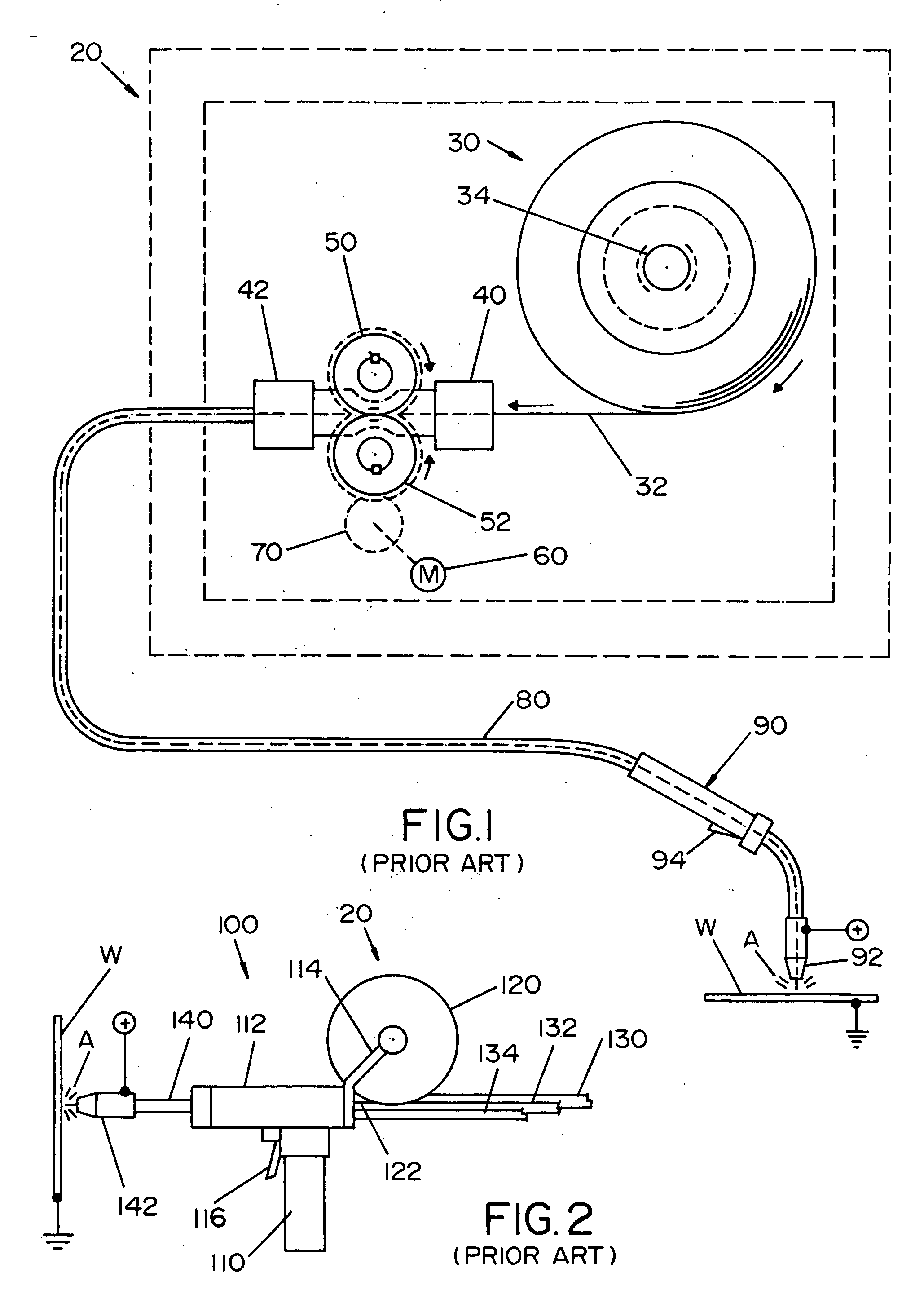
[0048] Referring now to the drawings, wherein the showings are for the purposes of illustrating the preferred embodiments of the invention only and not for the purpose of limiting the same, FIGS. 1 and 2 illustrate a prior art wire feeder 20 and a prior art welding gun 100, respectively. Prior art wire feeder 20 is representative of a wire feeder integrated in a welding unit, not shown, such as, but not limited to, the Power MIG 225 offered by The Lincoln Electric Company, or a stand alone wire feeder that is used in conjunction with a welding unit, not shown, such as, but not limited to, the LF 72 Wire Feeder offered by The Lincoln Electric Company; however, the wire feeder is not limited to these two models of welding units or stand-alone wire feeders.

[0049] Stand-alone or integrated wire feeder 20 includes a reel or spool 30 of welding wire 32 rotatably positioned on a spindle 34. The welding wire 32 is feed into a wire guide 40 that directs the welding wire to drive rollers 50,...


PUM

PropertyMeasurementUnit
Polarityaaaaaaaaaa
Coloraaaaaaaaaa
Tensionaaaaaaaaaa

Abstract

A modular welding wire feed drive for use in a welding system. The welding wire feed drive is designed to be detachably connected to the welding wire feed system of the welding system. The welding wire feed drive includes a drive housing designed to be detachably connectable to the welding wire feed system, a wire contact arrangement designed to controllably feed welding wire through the welding wire feed drive, and a drive motor that is connected to or interconnected to the wire contact arrangement to at least partially drive the wire contact arrangement.

Description

[0001] The present invention is related to the art of welding and more particularly to welders that include the use of wire feeders. BACKGROUND OF THE INVENTION [0002] Wire feeders for electric arc welders typically include a welding wire drive assembly that pulls welding wire from a welding wire source (e.g., wire spool, canister of wire, etc.) and then feeds the welding wire to the welding gun. The wire drive assembly typically includes one or more drive wheels that pull and push the welding wire at a desired or controlled wire feed speed so that the proper amount of molten metal is deposited on a workpiece during the formation of a weld bead or the like. [0003] Two general configurations are used to feed welding wire to the welding gun. In one configuration, the wire feeder is connected to or integrated with the welder. In this configuration, the wire feeder includes an integrated motor, drive rollers, gears, and wire guides designed to draw the welding wire from a welding wire s...

Claims


Application Information

Patent Timeline
IPC IPC(8): B23K9/12
CPCB23K9/1336
Inventor DIEKMANN, CRAIG L.PERRIN, DAVID W.
Owner LINCOLN GLOBAL INC
Why Eureka
Try Eureka