
Compound polarization beam splitters

a polarization beam and beam splitter technology, applied in the field of optical assemblies, can solve the problems of reducing the contrast of the system, adding cost, and depolarizing the transmitted light caused, and achieve the effect of simple and less expensive construction, short back focal length

Inactive Publication Date: 2005-06-30
3M INNOVATIVE PROPERTIES CO
View PDF29 Cites 9 Cited by
  • Summary
  • Abstract
  • Description
  • Claims
  • Application Information

AI Technical Summary

Benefits of technology

[0023] (1) the PBS is easy to manufacture and does not require thin or ultra-flat substrates;
[0027] As an additional fifth property, the optical path through the PBS for imaging light is preferably short so that the projection lens which forms the ultimate image can have a shorter back focal length and thus a simpler and less expensive construction.

Problems solved by technology

The main problem with using a MacNeille-type PBS in image projection systems is the depolarization of transmitted light that is caused by skew-ray effects.
This depolarized light reduces the contrast of the system.
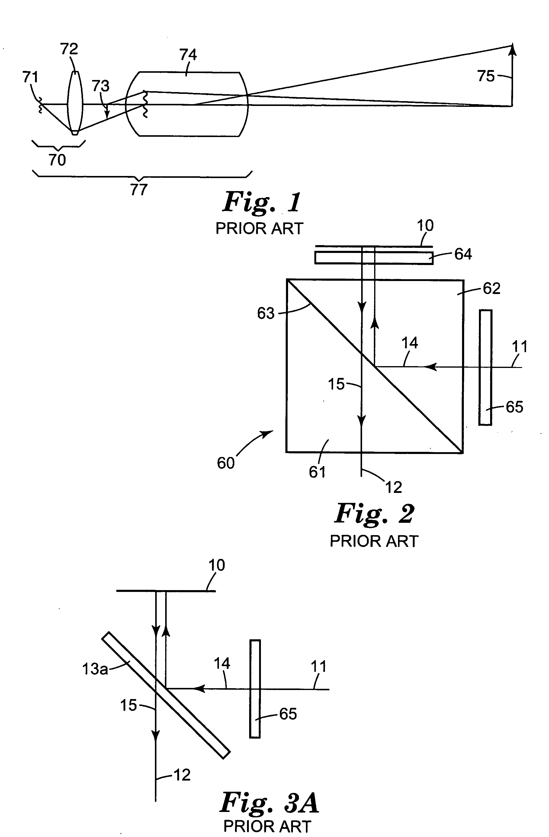
In accordance with the Miyatake patent, compensation of the skew-ray depolarization requires an additional quarter-wave plate (i.e., plate 64 in FIG. 2), which adds cost, requires precision alignment, and restricts the range of operating temperatures.
Unfortunately, both of these layouts suffer from optical problems.
The optical problem associated with the layout of FIG. 3A is that there is a tilted plano-parallel plate in the imaging optical path.
Currently, a technological limitation in the process that creates the wire grid structure makes the use of a thinner substrate difficult.
Therefore, the layout of FIG. 3A has unacceptable image quality due to astigmatism that is 2.5-3 times larger than the depth of focus.
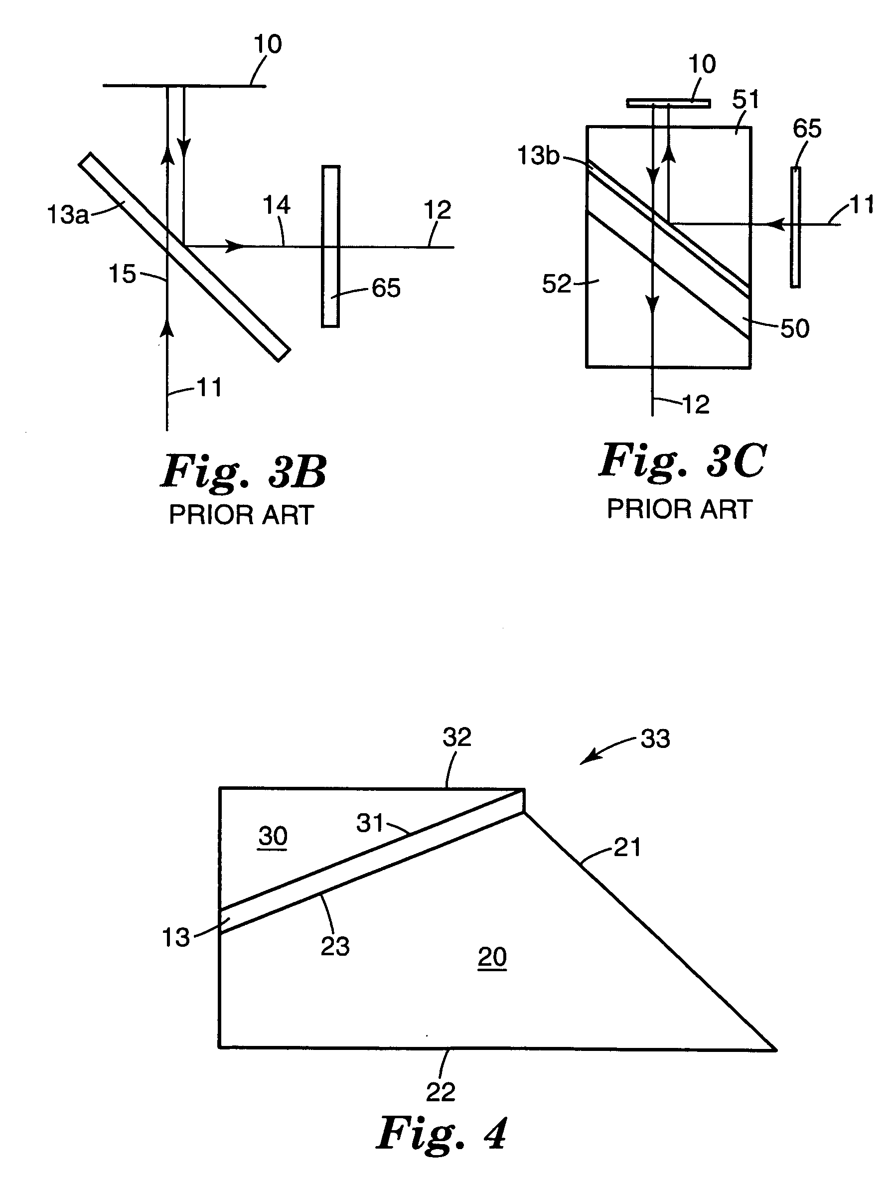
There are also two other problems associated with the layout of FIG. 3B: (1) temperature deformation and (2) wire grid structure protection.
This elevated temperature can create deformation of the wire grid substrate, which will degrade the image quality on the screen.
However, the use of such an astigmatism corrector significantly increases the cost of the PBS.

Method used


Image

  • Compound polarization beam splitters
  • Compound polarization beam splitters
  • Compound polarization beam splitters

Examples


Embodiment Construction

[0099] As discussed above, the present invention relates to a prism assembly which utilizes the excellent polarization properties of Cartesian polarizers, including wire grid polarizers and multi-layer reflective polarizers, and can be used with, for example, a LCoS-based projection system with the following advantages: [0100] (1) no special requirements are imposed on the wire grid substrate, specifically, no thickness restrictions and no need for ultra-flatness; [0101] (2) complete environmental protection is provided for the wire grid structure; [0102] (3) there is no potential for deformation of the polarizer at elevated temperatures; [0103] (4) in the case of multi-layer reflective polarizers, the system has significantly reduced astigmatism thus reducing or eliminating the need for an astigmatism corrector; and [0104] (5) the imaging optical path inside of the prism assembly has reduced length compared to conventional PBSs.

[0105] In broadest terms, the invention is a compound...


PUM


Abstract

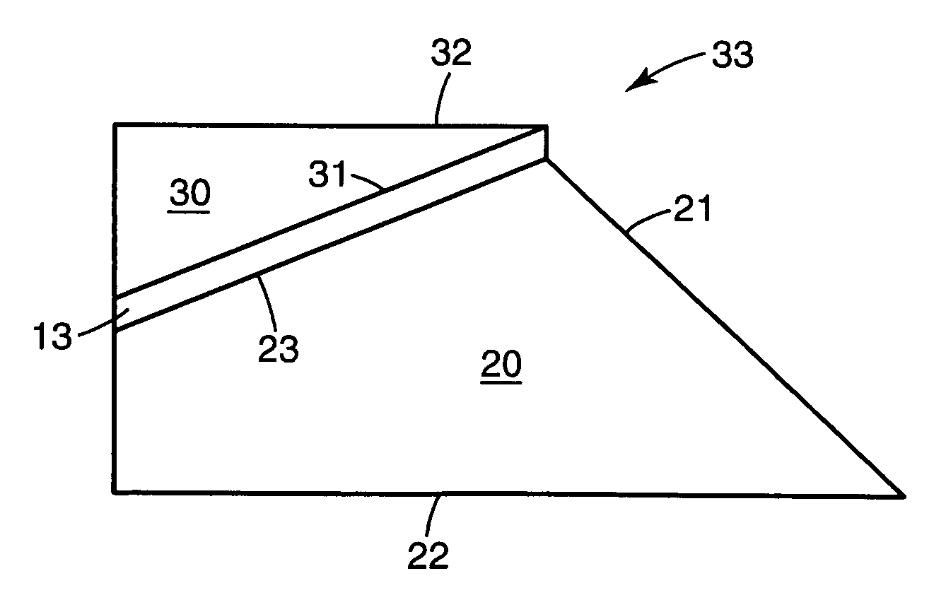
A compound polarization beam splitter (33) for use with a reflective, polarization-modulating, imaging device (10), e.g., a LCoS device, is provided. The compound PBS has: (a) an input prism (20); (b) an output prism (30), and (c) a polarizer (13), which is located between the two prisms (20,30) and which may be a wire grid polarizer (13a) or a multi-layer reflective polarizer (13b). Polarized illumination light (11) enters the input prism (20) through a first surface (21) and undergoes total internal reflection at a second surface (22) before being reflected from the polarizer (13) and polarization-modulated at the imaging device (10). The polarizer's tilt angle (β) is less than 45°, which reduces astigmatism and the required back working distance of the system's projection lens (74).

Description

CROSS REFERENCE TO RELATED PROVISIONAL APPLICATION [0001] This application is a continuation of U.S. patent application Ser. No. 10 / 822,397, filed Apr. 12, 2004, which is a continuation of U.S. patent application Ser. No. 10,374,221, filed Feb. 25, 2003, now U.S. Pat. No. 6,719,426, which claims the benefit under 35 USC §119(e) of U.S. Provisional Application No. 60 / 361,190, filed Feb. 28, 2002. The contents of these patent applications are incorporated herein in their entirety.FIELD OF THE INVENTION [0002] This invention relates to optical assemblies (optical units) for the effective polarization separation of light. The assemblies can be used with, for example, reflective liquid crystal on silicon devices (LCOS devices). [0003] More specifically, the invention relates to polarization separation devices known as polarization beam splitters (also referred to in the art as “polarized beam splitters,”“polarizing beam splitters,” or simply “PBSs”) and, in particular, to polarization be...

Claims


Application Information

Patent Timeline
Patent Type & Authority Applications(United States)
IPC IPC(8): G02B5/30G02B5/04G02B27/28G03B21/00
CPCG02B5/3033G02B27/283G02B5/3058G03B21/28G02B27/28
Inventor MAGARILL, SIMONBRUZZONE, CHARLES L.ECKHARDT, STEPHEN K.ENGLISH, R. EDWARD JR.FULKERSON, E. GREGORYMA, JIAYINGRUTHERFORD, TODD S.
Owner 3M INNOVATIVE PROPERTIES CO
Learn More