
Rotatable latching device for a housing of a portable electronic device

a portable electronic device and latching device technology, which is applied in the direction of instruments, wing accessories, casings/cabinets/drawer details, etc., can solve the problems of difficult to operate with a user's fingers without errors, and it is difficult for some users to readily identify the particular functions of keys

Inactive Publication Date: 2005-06-23
MOTOROLA INC +1
View PDF2 Cites 56 Cited by
  • Summary
  • Abstract
  • Description
  • Claims
  • Application Information

AI Technical Summary

Benefits of technology

[0016] Preferably, said cam element comprises two or m

Problems solved by technology

There are, however, practical limitations to the extent to which many such portable electronic devices can be miniaturised without interfering with ease and convenience of use.
For example, while a keypad readily may be miniaturised, it becomes difficult to operate with a user's fingers without errors due to simultaneous touching of closely adjacent keys.
With miniaturised keypads, there is usually associated miniaturised indicia on or adjacent the keys which may make it difficult for some users to readily identify the particular functions of keys.
Importantly however, miniaturisation of keypads in particular makes it much more difficult for a user to operate the device with a single hand.
A limitation of telescopically extendible two part housings is that to retain a robust coupling of the housing members, a substantial degree of overlap must be retained in the extended position, thereby substantially limiting the amount by which the housing may be extended.
A disadvantage with flip type or clam shell portable electronic devices having a spring biased flip cover member is that robust stop members are required to avoid damage to the flip cover member and its associated hinge as it reaches the limit of its open position.
Moreover, even robust latch mechanisms are prone to wear or breakage which can render an otherwise fully functional portable electronic device as useless or too inconvenient for further use, particularly when the flip cover member is coupled to an on-off switch for the device.

Method used


Image

  • Rotatable latching device for a housing of a portable electronic device
  • Rotatable latching device for a housing of a portable electronic device
  • Rotatable latching device for a housing of a portable electronic device

Examples


Embodiment Construction

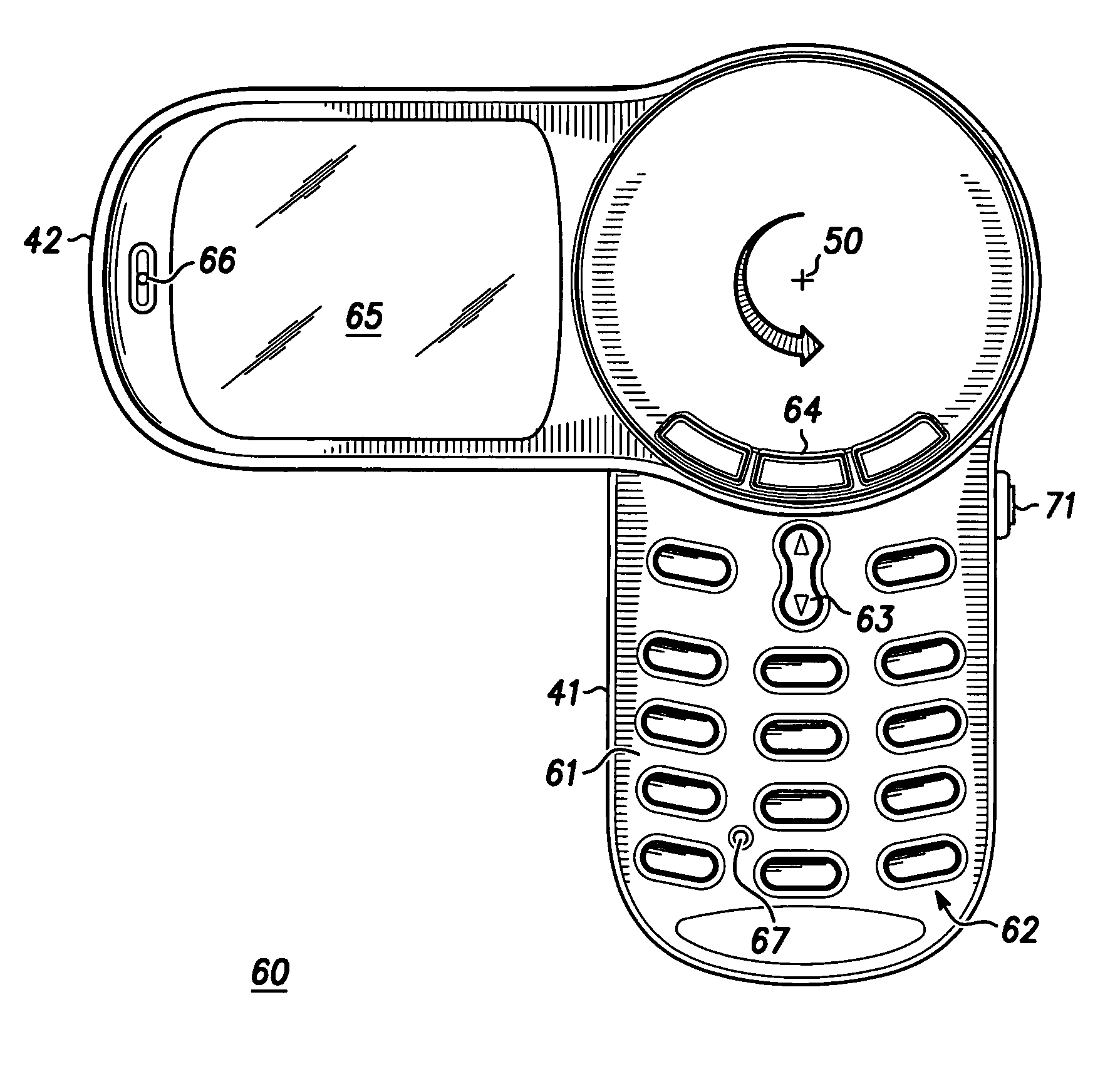
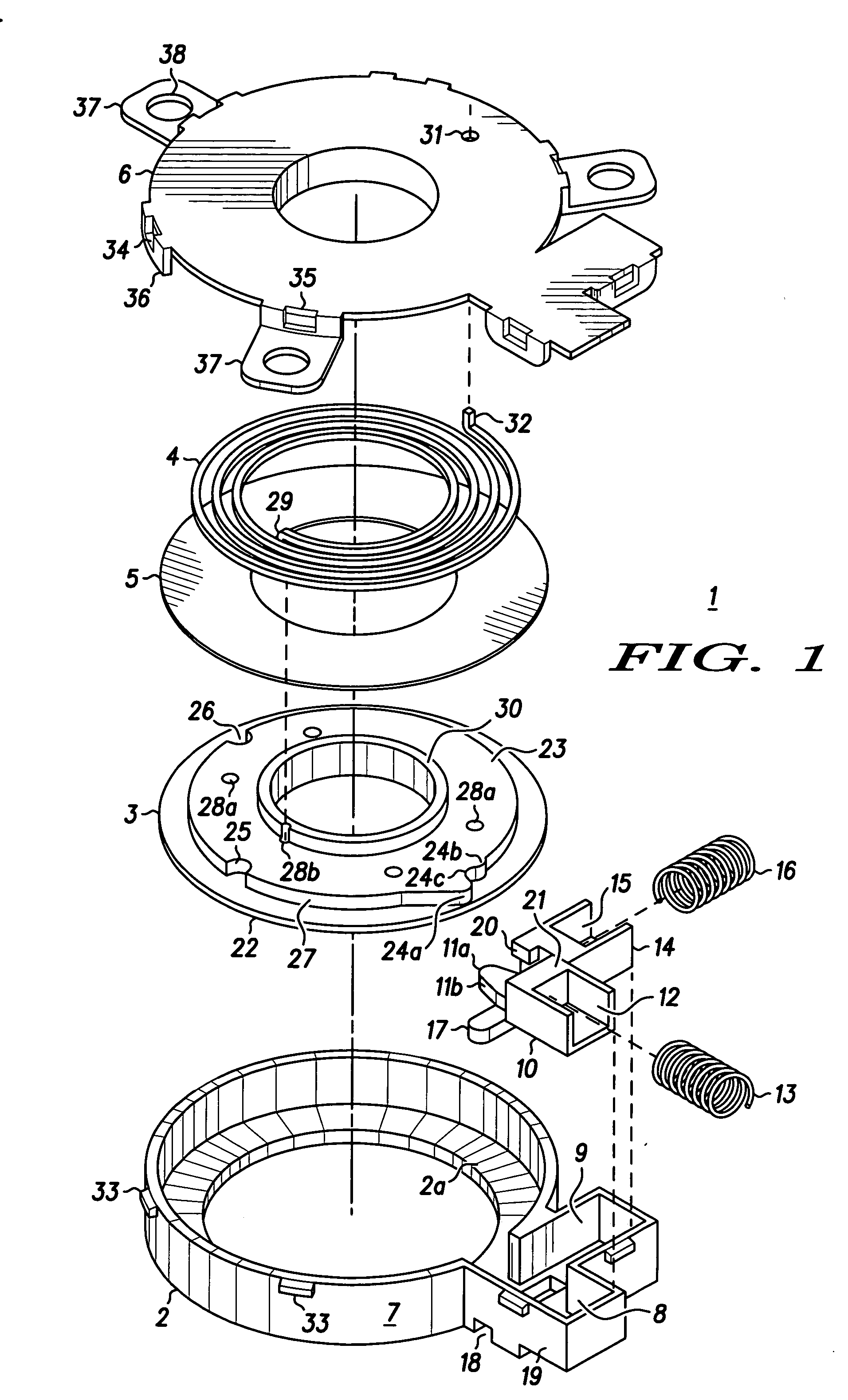
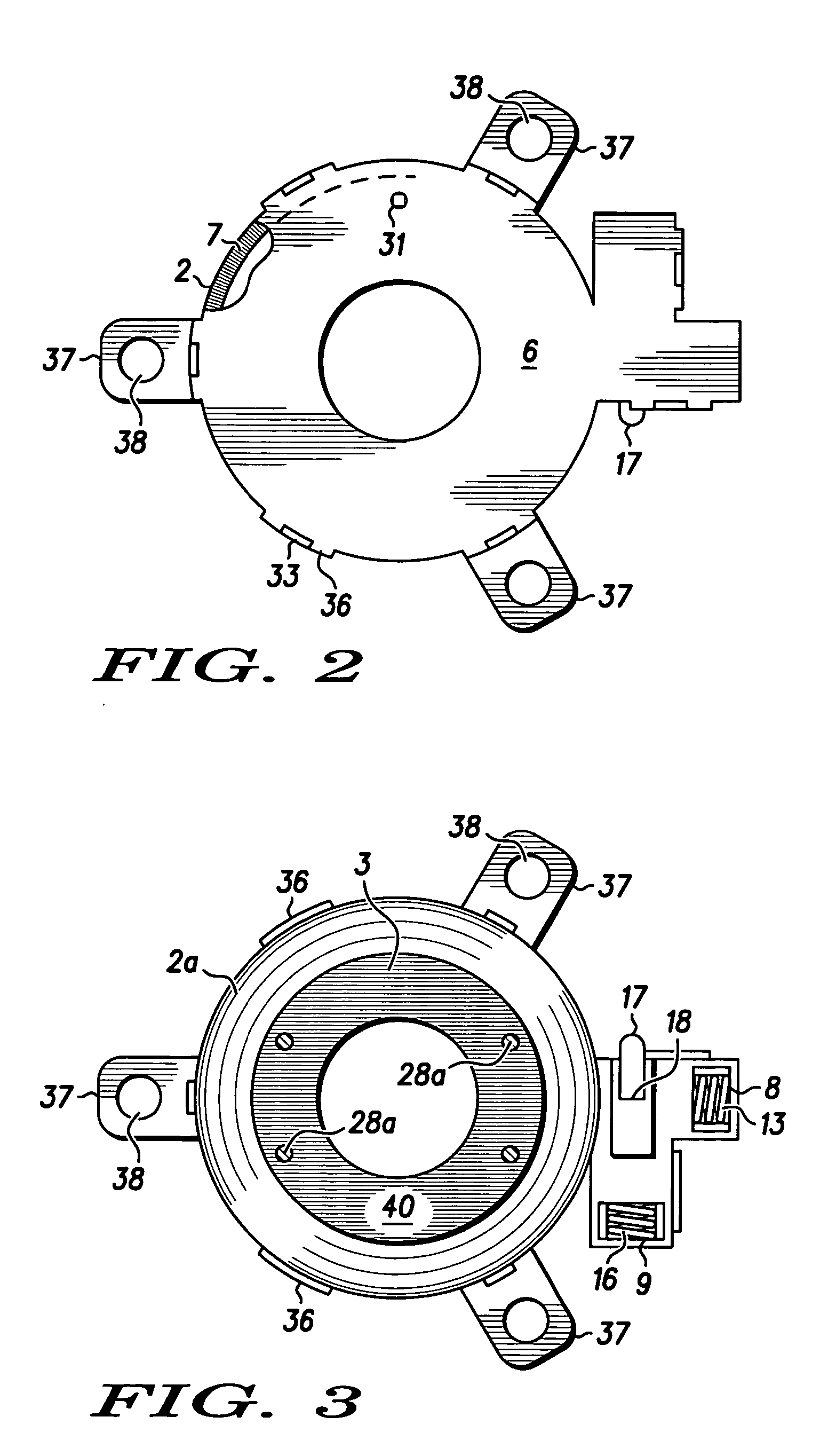
[0052] In the description of the preferred embodiments illustrated in the accompanying drawings, like reference numerals will be employed for like features where appropriate. FIG. 1 shows a rotatable latching device 1 comprising a body 2, a substantially circular rotatable cam element 3, a torsional biasing member 4 in the form of a coil spring, a bearing plate 5 and a cover plate 6. Body 2 comprises an annular retaining flange 2a and a substantially circular outer wall 7 with a radially extending detent follower cavity 8 projecting therefrom. Extending perpendicularly to and communicating with detent follower cavity 8 is a latch mechanism cavity 9.

[0053] A detent follower 10, locatable in cavity 8, includes a nose member 11a having an engaging surface 11b formed on an edge of the nose member 11a. A hollow recess 12 extending rearwardly of detent follower 10 receivably locates a resilient biasing member 13 in the form of a compressible coil spring. A latching mechanism 14 also has ...


PUM


Abstract

A rotatable latching device (1) for a portable electronic device (60) having a two part housing wherein a first housing member (42) rotates relative to a second housing member (41) about an axis (50) substantially perpendicular to a front surface (61) of the device. The latching device (1) has a body (2) securable within and to the second housing member (41) and the first housing member (42) is mounted to a rotatable cam element (3) located within the body (2) and is rotatable with the cam element (3) continuously from a closed position to an open position 180° to the closed position by a torsion spring (4) after manually disengaging a latchable detent follower (10). During manual return from an open position to a closed position, housing member (41) is latchable in an intermediate position at 90° to a closed position to enable selective viewing of a display mounted to said first housing member (42).

Description

FIELD OF THE INVENTION [0001] This invention is concerned with latching devices and two part housings for portable electronic employing such latching devices wherein one housing member is movable between an open and closed position. [0002] The invention is concerned particularly although not exclusively with two part housing latching devices and two part housings for a wireless communications device wherein one housing member is rotatable relative to the other housing member about a rotational axis perpendicular to a front surface of the device. BACKGROUND ART OF THE INVENTION [0003] Portable electronic devices these days offer a wide range of functionalities to suit the diverse needs of users of such devices. Whilst incorporating a greater range of functionalities into such devices, there has been a strong trend to miniaturisation to enable the devices to be more conveniently carried by a user, whether in a pocket or a purse, whether carried on a belt clip or even on a lanyard susp...

Claims


Application Information

Patent Timeline
IPC IPC(8): E05D11/10G12B9/04H04M1/00H04M1/02H05K5/02H05K7/18
CPCE05D11/1007E05D11/1064H04M1/0243H04M1/0227E05Y2900/606E05Y2999/00
Inventor TOH, KOK WAHCHOW, TATT HOONGGOVINDAN, MANOJLEE, YIK BINTEO, BOON KIAT
Owner MOTOROLA INC
Learn More