Eureka AIR delivers breakthrough ideas for toughest innovation challenges, trusted by R&D personnel around the world.

Peer-to-peer system and method with prefix-based distributed hash table

a distributed hash table and peer-to-peer technology, applied in the field of distributed systems, can solve the problems of long routing paths and systems with poor utilization, not being suitable for commercial p2p applications, and not being able to meet the requirements of p2p applications

Inactive Publication Date: 2005-06-23
NEC CORP
View PDF21 Cites 62 Cited by
  • Summary
  • Abstract
  • Description
  • Claims
  • Application Information

AI Technical Summary

Benefits of technology

This patent describes a way to create a secure and efficient peering system where data is shared between users without compromising its privacy. It uses a unique method called hashing to identify different parts of data and ensures that all traffic within the system stays on a specific path. This prevents any issues like slow downs or delays when transferring large amounts of data. Overall, this technology allows for faster and more reliable communication among peers while keeping things organized and safe.

Problems solved by technology

The patent text discusses the need for improved storage systems that use distributed hash tables. The current generation of file sharing systems, like NAPSTER and GNUTELLA, had scalability issues. To address this, research groups have proposed new generations of scalable P2P systems based on DHTs. However, these systems have poor utilization due to long routing paths and ad-hoc and dynamic nature of conventional P2P networks. Therefore, there is a need for a new type of distributed hash table architecture that takes advantage of stable dedicated resources to offer better performance than traditional P2P systems.

Method used


Image

  • Peer-to-peer system and method with prefix-based distributed hash table
  • Peer-to-peer system and method with prefix-based distributed hash table
  • Peer-to-peer system and method with prefix-based distributed hash table

Examples


Embodiment Construction

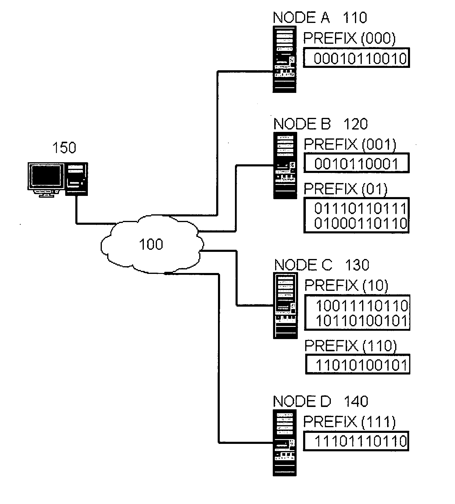
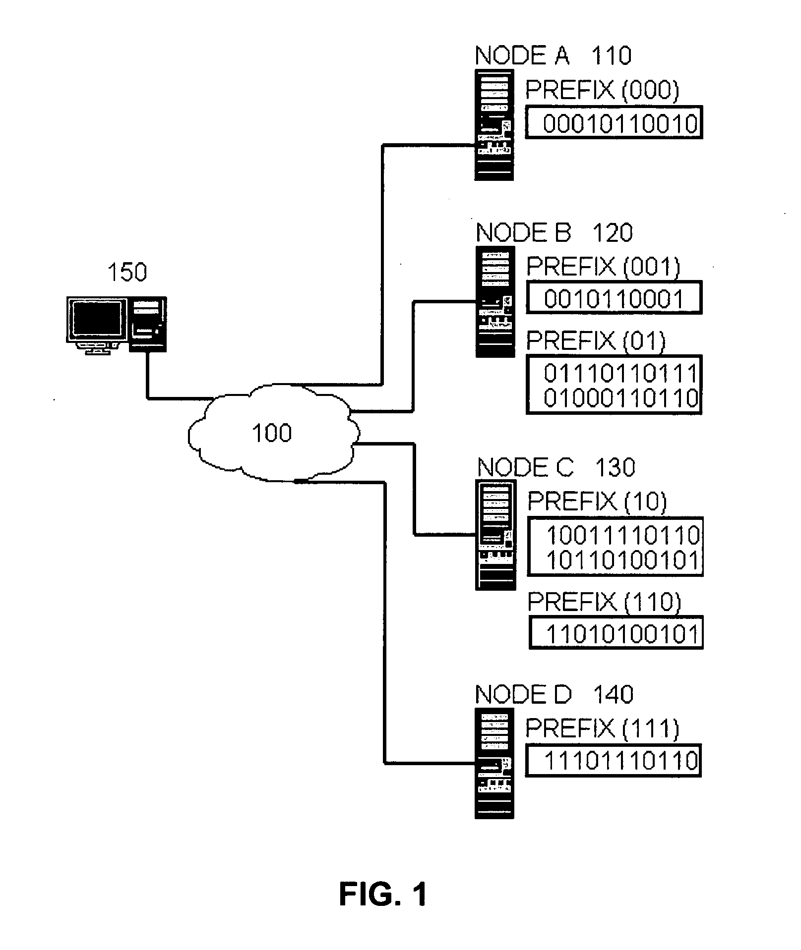
[0016]FIG. 1 is a diagram of a commercial peer-to-peer system, configured in accordance with an embodiment of an aspect of the invention. A plurality of physical nodes, illustratively 110, 120, 130, 140, communicates with each other through an underlying transport network 100. There is no restriction on the location or grouping of the physical nodes 110, 120, 130, 140 with regards to the present invention. The physical nodes can vary in actual storage space, processing power, and other resources.

[0017] The physical nodes preferably arrange their storage capacity in what the inventors refer to as a number of fixed size “slots” which can be roughly proportional to the amount of storage available to the physical node. Each physical node is responsible for the storage and retrieval of one or more objects, each object associated with a preferably fixed-size hash key of a hash function. Any advantageous hashing function that maps objects to a fixed-size hash key can be utilized in the co...


PUM


Abstract

An architecture for a peer-to-peer network is disclosed which advantageously is able to maintain short fixed path length routing as the network grows.

Description


Claims


Application Information

Patent Timeline
Owner NEC CORP
Why Eureka
Eureka Blog
Learn More