
Network information setting method, network system and communication device

a network information and communication device technology, applied in the field of network information setting method, network system and communication device, can solve the problems of inability to effectively protect the network against the attack of malicious third parties, inability to assume a particular layer-b>2/b> technique, and inability to assume a closed network, etc., to achieve convenient control of the network, safe and autonomous device setting, and not take a lot of time for setting

Inactive Publication Date: 2005-06-23
KK TOSHIBA +1
View PDF14 Cites 14 Cited by
  • Summary
  • Abstract
  • Description
  • Claims
  • Application Information

AI Technical Summary

Benefits of technology

The present invention provides a method, system, and device that allow devices to be safely and autonomously connected to a control network. This is done by initializing property information of a device in a server when it is connected to the network and then transmitting the property information to another server through secure communication using key information. The technical effect of this invention is that it saves time and makes it easier to set up a control network with a large number of devices.

Problems solved by technology

Even if the control network has its own protocol and it is not open to the public, it is impossible to effectively protect the network against the attack by a malicious third party having explicit ill will.
Therefore, it is impossible to assume a closed network.
However, in order to effectively utilize the Internet technique, it is impossible to assume the particular layer-2 technique.
Therefore, the security technique depending on the particular layer 2 narrows the width of selection of the system configuration and increases the engineering cost.
It is inefficient to manually set information necessary for the operation with respect to a large number of devices distributed on the control network.
Further, it may cause errors.
The peripheral devices of the field devices are limited.

Method used


Image

  • Network information setting method, network system and communication device
  • Network information setting method, network system and communication device
  • Network information setting method, network system and communication device

Examples


first embodiment

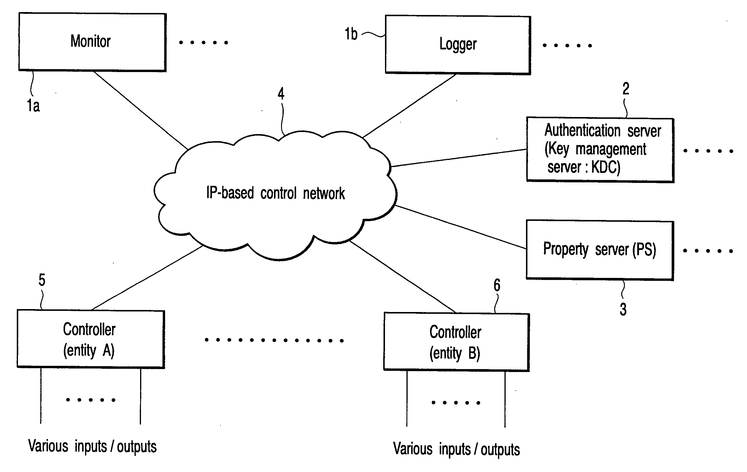
[0034] A first embodiment of the present invention relates to a network system which realizes automatic control (monitoring / controlling devices for production, prevention of disaster damage, illumination control and the like) in a plant or building. For automatic control, the system includes a subsystem having a plurality of devices. The subsystem devices corresponding to a monitoring system, data logger, sensor / actuator group are physically or logically widely arranged in a facility, connected to a control network and operated. As the control network, a network may be realized based on existing BACnet (trade mark), MODBUS (trade mark) or an IP network can be newly configured. It is preferable to use IPv6 in the IP network. It should be noted that the present invention is not limited to the application to the network system for automatic control in the plant or building.

[0035] The network system of this embodiment realizes an autonomous setup which makes unnecessary manual and trou...

second embodiment

[0076] The second embodiment of the present invention is more concrete than the first embodiment described above. FIG. 5 is a view showing a network system according to the second embodiment of the present invention. In the second embodiment, IPv6 is applied. Further, Kerberos is used for mutual authentication of devices, DHCP is used for detection of a KDC which is a key distribution server of Kerberos and IPsec is used for safety of communication between entities. In addition, KINK is used for dynamic key exchange necessary for the operation of IPsec.

[0077] Kerberos is a communication protocol which is defined by RFC1510. Kerberos provides a service to permit the entity on the network to make mutual authentication by use of the identifier. In this case, a term “identifier” does not indicate an IP address but indicates a name. In Kerberos, the substance of a device (entity) is referred to as a “principal”. Further, a logical area under management of certain Kerberos is referred to...


PUM


Abstract

Property information of a communication device is initialized in a second server when the communication device is connected to a control network to which a first server for storing key information and a second server for storing property information are connected. Key information necessary for security communication with respect to the second server is acquired from the first server and property information containing at least an identifier and network address of the communication device is transmitted to the second server via security communication using the key information.

Description

CROSS-REFERENCE TO RELATED APPLICATIONS [0001] This application is based upon and claims the benefit of priority from prior Japanese Patent Application No. 2003-368037, filed Oct. 28, 2003, the entire contents of which are incorporated herein by reference. BACKGROUND OF THE INVENTION [0002] 1. Field of the Invention [0003] The present invention relates to a network information setting method, network system and communication device in an IP-based control network. [0004] 2. Description of the Related Art [0005] The control network technique used in a building network or FA (Factory Automation) network starts to be provided at substantially the same time as the Internet which is rapidly popularized in recent years. However, it is developed according to its own line based on the particular condition such as the restriction on cost. Most of the control network techniques have protocol hierarchies which are based on the proprietary technique different from the Internet technique. Further...

Claims


Application Information

Patent Timeline
Patent Type & Authority Applications(United States)
IPC IPC(8): H04L9/08G06F13/00H04L12/66H04L29/06
CPCH04L63/061H04L63/0807H04L9/083H04L9/0844H04L63/0869
Inventor INOUE, ATSUSHIOKABE, NOBUOISHIYAMA, MASAHIROSAKANE, SHOICHI
Owner KK TOSHIBA
Learn More