
Vector 3-component 3-dimensional kirchhoff prestack migration

a technology of kirchhoff prestack migration and component, applied in the field of geophysical prospecting, can solve the problems of signal interference constructively at the correct image point, poor quality of subsurface images, and often suffering in spatial accuracy, resolution and coherence of obtained images

Inactive Publication Date: 2005-06-23
BAKER HUGHES INC
View PDF23 Cites 28 Cited by
  • Summary
  • Abstract
  • Description
  • Claims
  • Application Information

AI Technical Summary

Benefits of technology

[0019] The imaging operations may be performed by an onsite processor. Alternatively, processing may be done at a time different from the acquisition at a remote location. Data from the wellsite may be sent to the remote location by any suitable means, including a satellite link or by an Internet connection. The instructions enabling the processor to access the multicomponent seismic data and perform the 3C-3D migration processing may reside on a machine readable memory device. These instructions enable the processor to access the data and to process the data.

Problems solved by technology

The obtained image often suffers in spatial accuracy, resolution and coherence due to the long and complicated travel paths between source, reflector, and receiver.
In particular, due to the two-way passage of seismic signals through a highly absorptive near surface weathered layer with a low, laterally varying velocity, subsurface images may be of poor quality.
If the velocity model is reasonably accurate, the signals will interfere constructively at the correct image point.
As noted by Bicquart, Kirchhoff and other wide angle migration methods are sensitive to velocity error.
Velocities are difficult to obtain accurately in surface reflection seismology thus limiting the effectiveness of Kirchhoff migration in structures associated with steep dips.
This asymmetry requires considerable effort in computing weighting factors.
A limitation of the teachings of Hokstad is that they do not address the real world problem of 3-D seismic imaging.
While the results derived by Hokstad are quite elegant, the examples are limited to 2-D data and do not offer any practical suggestion of dealing with 3-D multicomponent data.

Method used


Image

  • Vector 3-component 3-dimensional kirchhoff prestack migration
  • Vector 3-component 3-dimensional kirchhoff prestack migration
  • Vector 3-component 3-dimensional kirchhoff prestack migration

Examples


Embodiment Construction

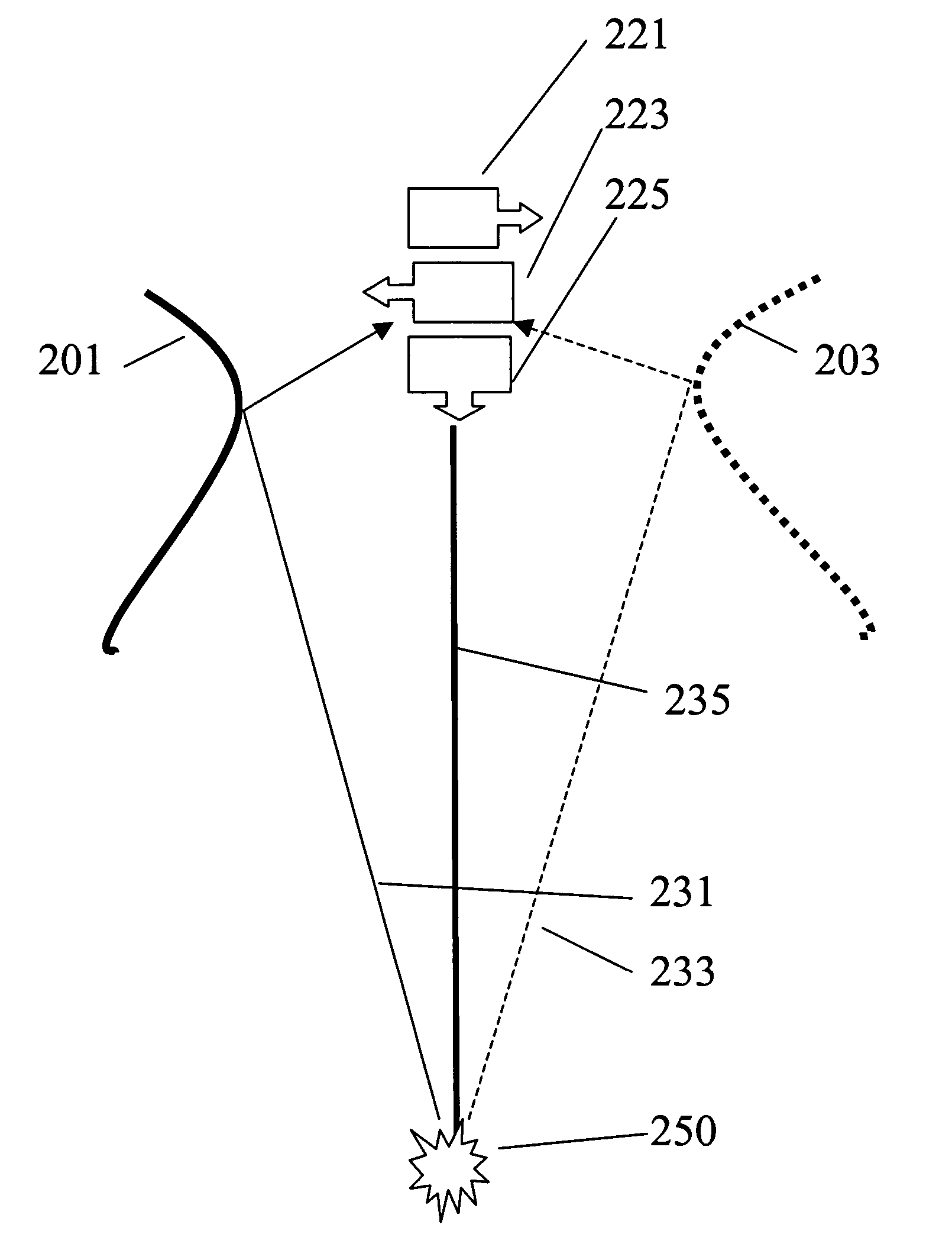
[0034] For the present invention, a modified version of the prior art system shown in FIG. 1 is used. The receiver 12 comprises an array of spaced apart receivers. Typically, 5-80 receivers are used. Each receiver comprises a three-component (3-C) receiver. In one embodiment of the invention, the three components are labeled H1, H2 and Z components, the Z component being vertical, and the H1 and H2 axes are orthogonal to the Z axis and orthogonal each other. The receivers may be gimbal mounted. This facilitates use of the receivers in a deviated borehole. With such an arrangement, the mechanical construction of the horizontal component receivers is usually different from the mechanical construction of the Z component receiver due to the fact that the latter has gravity acting along the direction of motion of the receivers. Either geophones or accelerometers may be used. In an alternate embodiment of the invention, the three receivers are substantially identical in sensitivity and ar...


PUM


Abstract

An apparatus and a method for migration of three components, 3-Dimensions seismic (3-C, 3-D) data acquired by down-hole receivers and surface seismic sources. This method utilizes full 3 components reflection wave field. It uses a dynamic, vector energy mapping method to image a reflection position and maps each time sample only to its reflected image point. Therefore, this method reduces unwanted data smearing and false mirror images. This method overcomes the weakness of using only a single component trace or pre-rotated three-component traces in the 1-C or 3-C 3-D VSP migration and produces better 3-D image.

Description

CROSS-REFERENCES TO RELATED APPLICATIONS [0001] This application claims priority from U.S. Provisional Patent Application Ser. No. 60 / 515,107 filed on Oct. 28, 2003 and U.S. Provisional Patent Application Ser. No. 60 / 576,526 filed on Jun. 3, 2004.BACKGROUND OF THE INVENTION [0002] 1. Field of the Invention [0003] This invention relates to a method of geophysical prospecting which improves the accuracy of seismic migration. Specifically, the invention uses offset or zero-offset survey measurements to accurately migrate reflectors present in three-dimensional (3-D) surface seismic data, in Vertical Seismic Profiles (VSPs), and in cross-well seismic survey data. [0004] 2. Description of the Related Art [0005] In surface seismic exploration, energy imparted into the earth by a seismic source reflects from subsurface geophysical features and is recorded by a multiplicity of receivers. This process is repeated numerous times, using source and receiver configurations which may either form ...

Claims


Application Information

Patent Timeline
IPC IPC(8): G01V1/28G01V1/30G01V1/36
CPCG01V1/28G01V2210/51G01V1/305G01V1/284G01V1/42
Inventor WANG, DAPENG
Owner BAKER HUGHES INC
Learn More