
Flexible tinsel ribbon antenna and assembly method for a tire

a technology of tinsel ribbon and antenna, which is applied in the direction of vehicle tyre testing, instruments, roads, etc., can solve the problems of destroying the utility of the tire, risk of damage to the annular antenna-transponder system, and difficulty in doing the job, so as to facilitate transportation and inventories, and increase the elongation of the antenna. , the effect of remarkable elongation

Inactive Publication Date: 2005-06-23
THE GOODYEAR TIRE & RUBBER CO
View PDF1 Cites 11 Cited by
  • Summary
  • Abstract
  • Description
  • Claims
  • Application Information

AI Technical Summary

Benefits of technology

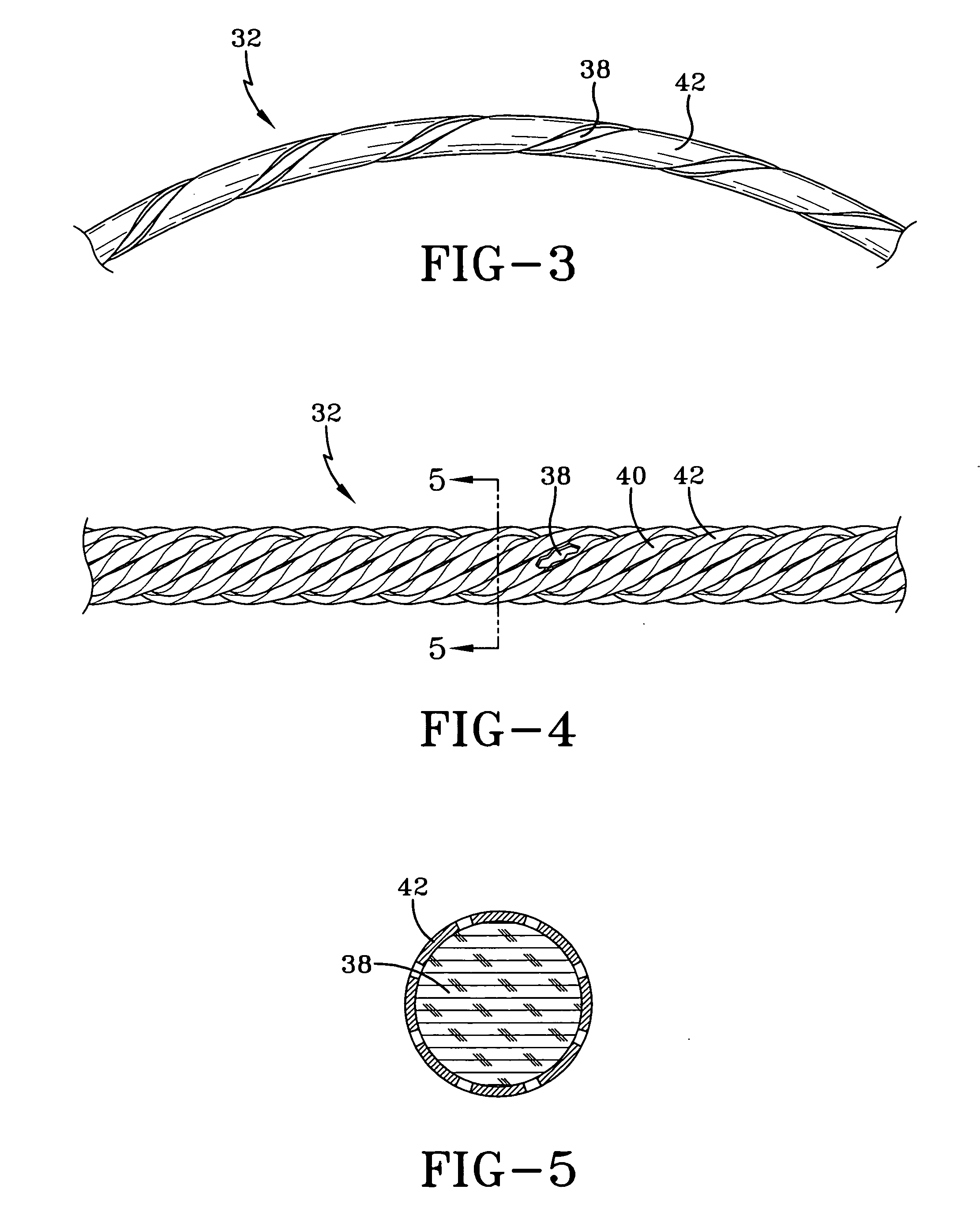
The invention provides a flexible conductor as an antenna in a tire monitoring system. The antenna cable is made from a conductive metal tinsel made by rolling a wire into a flat ribbon and twisting several strands together. The tinsel ribbons can elongate with the strength member, which is made of textile material like nylon or polyester. The elongation is dependent on the strength member. The strength member protects the integrity of the conductive tinsel ribbon antenna and allows for convenient transportation and inventorization. The invention improves metal fatigue resistance and maintains an optimal location of the antenna within a tire cavity. The method involves assembling a conductive ribbon antenna, attaching it to a strength member, and then attaching the antenna and strength member assembly into a pneumatic tire.

Problems solved by technology

While the antenna and transponder may be incorporated into a tire during “pre-cure” manufacture, in practice it is very difficult to do this.
Once assembled into the tire, any detected malfunction in the antenna, transponder, or antenna to transponder connection that cannot be repaired destroys the utility of the tire and may necessitate a scrapping of the tire.
Hence, placement of an annular antenna-transponder assembly into a tire during its manufacture carries risk that subsequent failure or breakage of assembly components will necessitate the destruction of the otherwise suitable host tire.
Not only is the risk of damage to an annular antenna-transponder system present during its incorporation into a tire during manufacture, but damage to such systems are not uncommon from operation of the tire on a vehicle.
Such locations represent high load and deformation to regions of the tire.
Consequently, antenna, transponders, and the connections therebetween in such locations are prone to breakage and mechanical or electrical failure.

Method used


Image

  • Flexible tinsel ribbon antenna and assembly method for a tire
  • Flexible tinsel ribbon antenna and assembly method for a tire
  • Flexible tinsel ribbon antenna and assembly method for a tire

Examples


Embodiment Construction

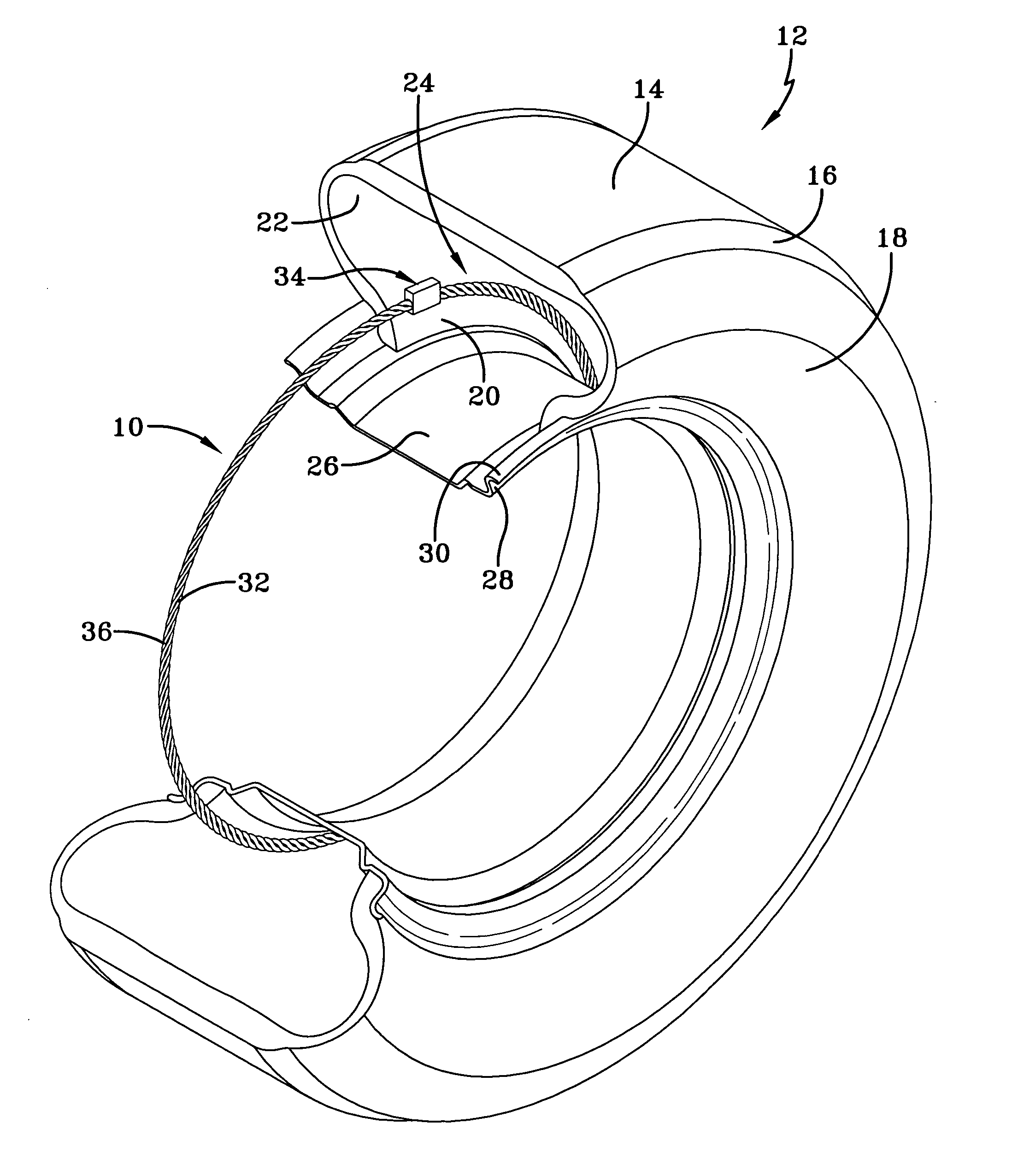
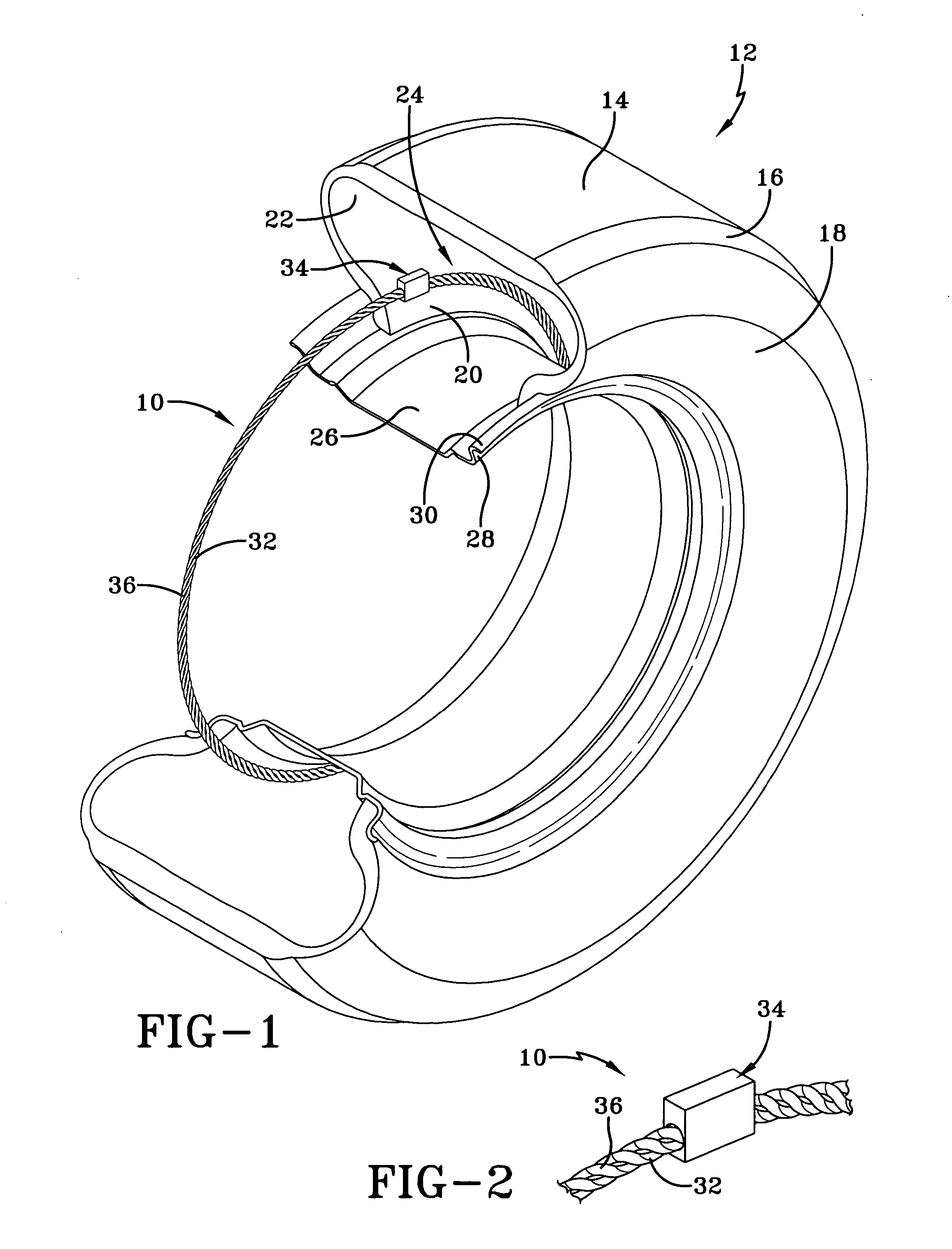
[0014] A tire pressure monitoring system typically consists of a transponder having one or more sensors. The transponder and associated electronics are housed within a package. In order to send or receive RF signals, a transponder must have an antenna. The antenna is preferably annular in configuration in the subject invention but may have alternative shapes if desired. The antenna may either be incorporated into the tire during manufacture or affixed to the tire by way of a post manufacture procedure. As used herein, an “annular antenna” may be circular, oblong, symmetrical, or asymmetrical without departing from the subject inventive principles. However, the preferred configuration of the antenna is circular and sized to overlap the tire sidewall region to which it attaches. The antenna may comprise a single wire or a plurality of strands. As explained below, the present invention deploys a conductive tinsel configuration in the formation of an antenna. Various commercially availa...


PUM


Abstract

An antenna system and method for tire monitoring systems provides a flexible conductor having sufficient elongation characteristics as an antenna in a tire monitoring sensor system. A conductive strand is formed by wrapping a conductive tinsel ribbon around an extensible strength member. One or more conductive strands are combined to form an antenna cable that affixes to the inner liner of a tire. According to one aspect of the invention a conductive strand is formed by spiral wrapping at least one conductive tinsel ribbon around the strength member. According to another aspect of the invention, multiple tinsel ribbons may be wrapped around the strength member in braided fashion.

Description

FIELD OF THE INVENTION [0001] The invention relates generally to an apparatus, including an antenna and a transponder, for a tire pressure monitoring system and, more specifically, to an elongated annular apparatus for incorporation into a tire pressure monitoring system. BACKGROUND OF THE INVENTION [0002] It is common to employ annular apparatus, including an antenna, for electronically transmitting tire or wheel identification or other data at radio frequency. The apparatus includes a radio-frequency transponder comprising an integrated circuit chip having data capacity at least sufficient to retain identification information for the tire or wheel. Other data, such as the inflation pressure of the tire or the temperature of the tire or wheel at the transponder location, can be transmitted by the transponder along with the identification data. [0003] It is known in the art to employ an annular antenna to transmit, at radio frequencies, data from a transponder contained within the s...

Claims


Application Information

Patent Timeline
Patent Type & Authority Applications(United States)
IPC IPC(8): B60C19/00B60C23/04H01Q1/22
CPCB29D2030/0072B29D2030/0077H01Q1/2241B60C23/0493H01Q1/22B60C19/00
Inventor STARINSHAK, THOMAS WALTER
Owner THE GOODYEAR TIRE & RUBBER CO
Learn More