Roof vent having labyrinth features
a technology of labyrinth and roof vent, which is applied in the direction of ventilation systems, lighting and heating apparatuses, heating types, etc., to achieve the effects of improving aesthetic features, improving rain exclusion features, and improving wind exclusion features
- Summary
- Abstract
- Description
- Claims
- Application Information
AI Technical Summary
Benefits of technology
Problems solved by technology
Method used
Image
Examples
second embodiment
[0070]FIG. 8 is a pictorial view of a flat roof vent assembly 110. As may be seen, this second embodiment does not include an external baffle such as 34 in the previous embodiment. Instead, the cowl 120 extends all the way towards its foot end so that it is substantially flush with the foot end of the base 130. This provides an aesthetically pleasing image. The cowl 120 can be attached to the base in the same manner as in the previous embodiment.
[0071]FIG. 9 is an exploded view of that shown in FIG. 8, showing some components thereof, namely the cowl 120 and the base 130. 134 is a large internal baffle, 135 is a first small internal baffle, and 136 is a second small internal baffle. As may be seen in this case, all three of the baffles are covered by the cowl. However, the relative shapes of the three baffles 134, 135, and 136 are similar to those of the previously discussed baffles 34, 35, and 36.
third embodiment
[0072]FIG. 10 is a pictorial view of a flat roof vent assembly 210. This assembly 210 includes a cowl 220 and a base 230. The assembly 210 also includes a cowl retention member not shown in this figure but illustrated later as 240 in FIG. 13.
[0073] The base 230 includes a floor plate 231 (which defines a lower major planar portion), a raised shelf 233 (which defines an upper major planar portion), and a front external baffle 234. The base also includes nailing locations 239 to receive nails for fastening the base to a supporting roof structure.
[0074] The cowl 220 includes downwardly oriented standoff feet 225 which bias on the top surface of the floor plate 231.
[0075]FIG. 11 is an isolated pictorial view of the base 230 of FIG. 10. It may be seen that there is an upturned peripheral wall 236 extending around the “quasi-pentagon” vent opening 232, which is defined by the base. The upturned wall 232 is configured to reduce the opportunity for water to pass therethrough; instead the ...
first embodiment
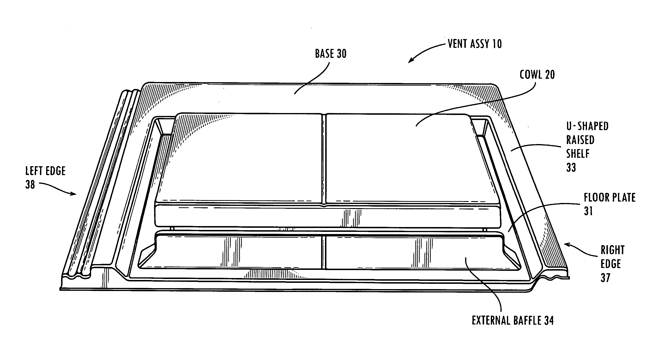
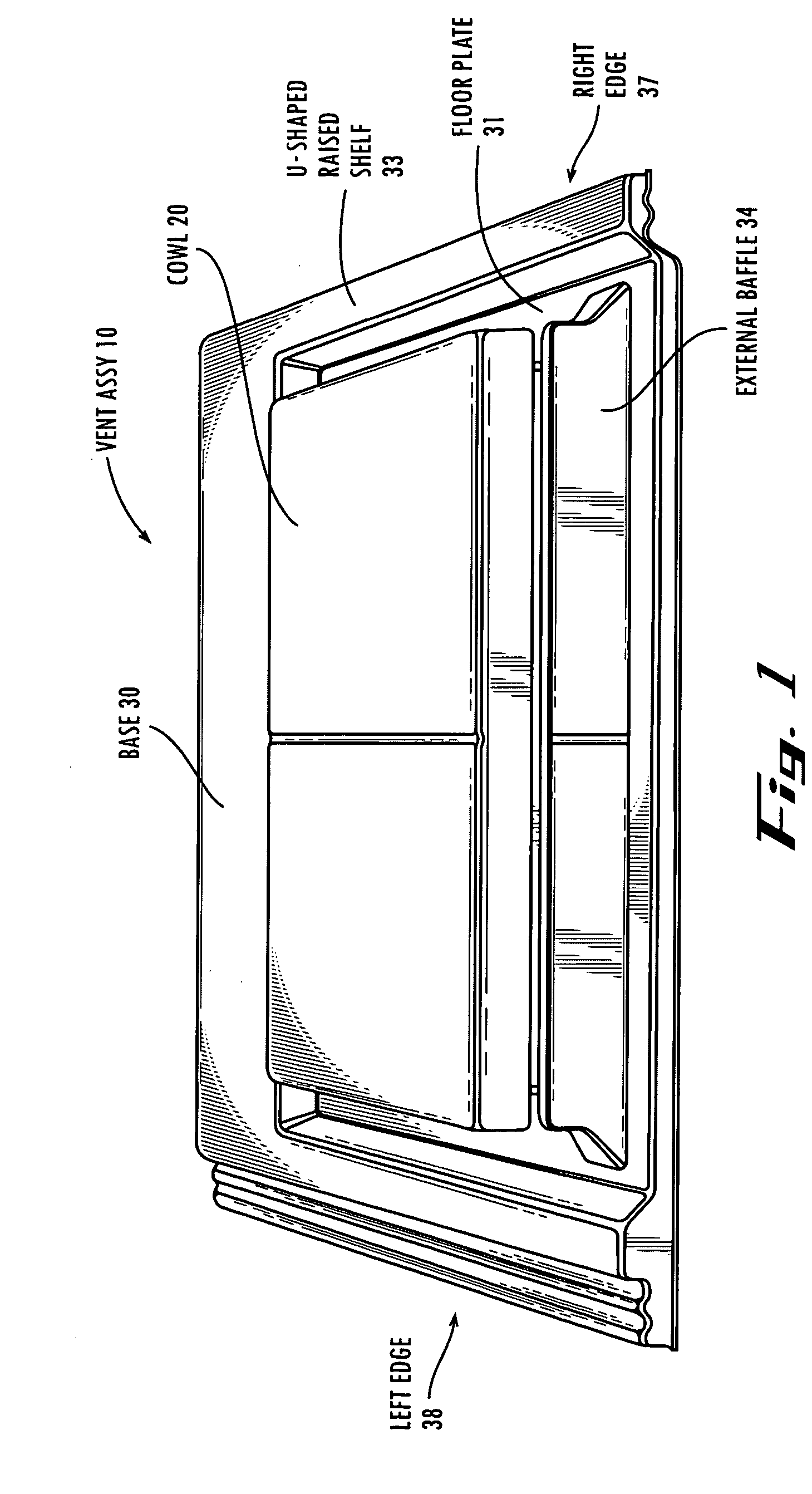
[0101] It should be understood that although certain combinations of internal and external baffles have been shown for purposes of indication, it should be understood that there are other alternative configurations that still manage to be covered by the present invention. For example, instead of using two small internal baffles, three or one internal baffles could be used; in fact, any reasonable number of internal baffles could be used within engineering limitations. At the same time, a large external baffle could be used as shown in the first embodiment, with the large external baffle having various height possibilities, depending on the severity of the weather of the application. Furthermore, the embodiments shown above discuss baffles with a vertical orientation. It should be noted that this is just one embodiment and in fact a horizontal labyrinth is also envisioned for the same purpose. Furthermore it could also be said that air passes “through” the labyrinth as opposed to “ov...
PUM
 Abstract
Description
Claims
Application Information
 - R&D
- Intellectual Property
- Life Sciences
- Materials
- Tech Scout
- Unparalleled Data Quality
- Higher Quality Content
- 60% Fewer Hallucinations
Browse by: Latest US Patents, China's latest patents, Technical Efficacy Thesaurus, Application Domain, Technology Topic, Popular Technical Reports.
© 2025 PatSnap. All rights reserved.Legal|Privacy policy|Modern Slavery Act Transparency Statement|Sitemap|About US| Contact US: help@patsnap.com


