
Injection nozzle, blast processing device and blast processing method with the injection nozzle, method of forming lubricating layer by the blast processing method, and sliding product with the lubricating layer formed by the method

Inactive Publication Date: 2005-06-16
FUJI MFG CO LTD
View PDF2 Cites 36 Cited by
  • Summary
  • Abstract
  • Description
  • Claims
  • Application Information

AI Technical Summary

Benefits of technology

[0123] An injection nozzle used for the conventional blast processing was a tapered nozzle where a cross section area of an aperture is gradually narrowed from the injection nozzle entrance to the exit, and the injection nozzle exit has the minimum cross section area.
[0124] Such tapered nozzle makes flow speed increase as the cross section of a gas flow path is getting narrower, and the gas flowing inside the nozzle has the maximum flow speed at the front end (nozzle exit) where the flow cross section area is the minimum.
[0125] However, expansion and acceleration of the gas flowing in the nozzle is possible in the range of a subsonic speed flow, and when a pressure difference in the gas between at the nozzle entrance and at the exit increases more than a predetermined value and reaches a critical state, even if the pressure difference becomes more than that, the gas flow speed does not change (choke). Therefore, it was not possible to increase the gas flow speed more than a critical flow speed, and even if the gas pressure in the nozzle entra

Problems solved by technology

The effect of this method, however, is restricted by the working environment in such a way that the lubricating effects can hardly be performed under the conditions of vacuum, ultrahigh/extremely low temperatures or the like.
However, in the method described in 11-315868, shooting solid lubricants to a dish-type spring as a work piece requires steel balls having hardness equivalent to or more than that of the work piece, and therefore, a lubricating layer can not be formed only by use of solid lubricants.
Furthermore, in the method described in 08-19695, although a lubricating layer can be formed by only solid lubricants and a rolling object as a work piece, it is necessary to put the work pieces together with solid lubricant into a ball mill container to rotate, resulting a problem that shapes and sizes of potential work pieces are extremely limited.
However, in the method described in Ogiwara, since the solid lubricants are penetrated into the work piece only by collision energy of the injected solid lubricants on the work piece surface, the energy needs to be quite huge.
As a result, the solid lubricant used as an injection material is limited to molybdenum disulfide having a

Method used


Image

  • Injection nozzle, blast processing device and blast processing method with the injection nozzle, method of forming lubricating layer by the blast processing method, and sliding product with the lubricating layer formed by the method
  • Injection nozzle, blast processing device and blast processing method with the injection nozzle, method of forming lubricating layer by the blast processing method, and sliding product with the lubricating layer formed by the method
  • Injection nozzle, blast processing device and blast processing method with the injection nozzle, method of forming lubricating layer by the blast processing method, and sliding product with the lubricating layer formed by the method

Examples


Example

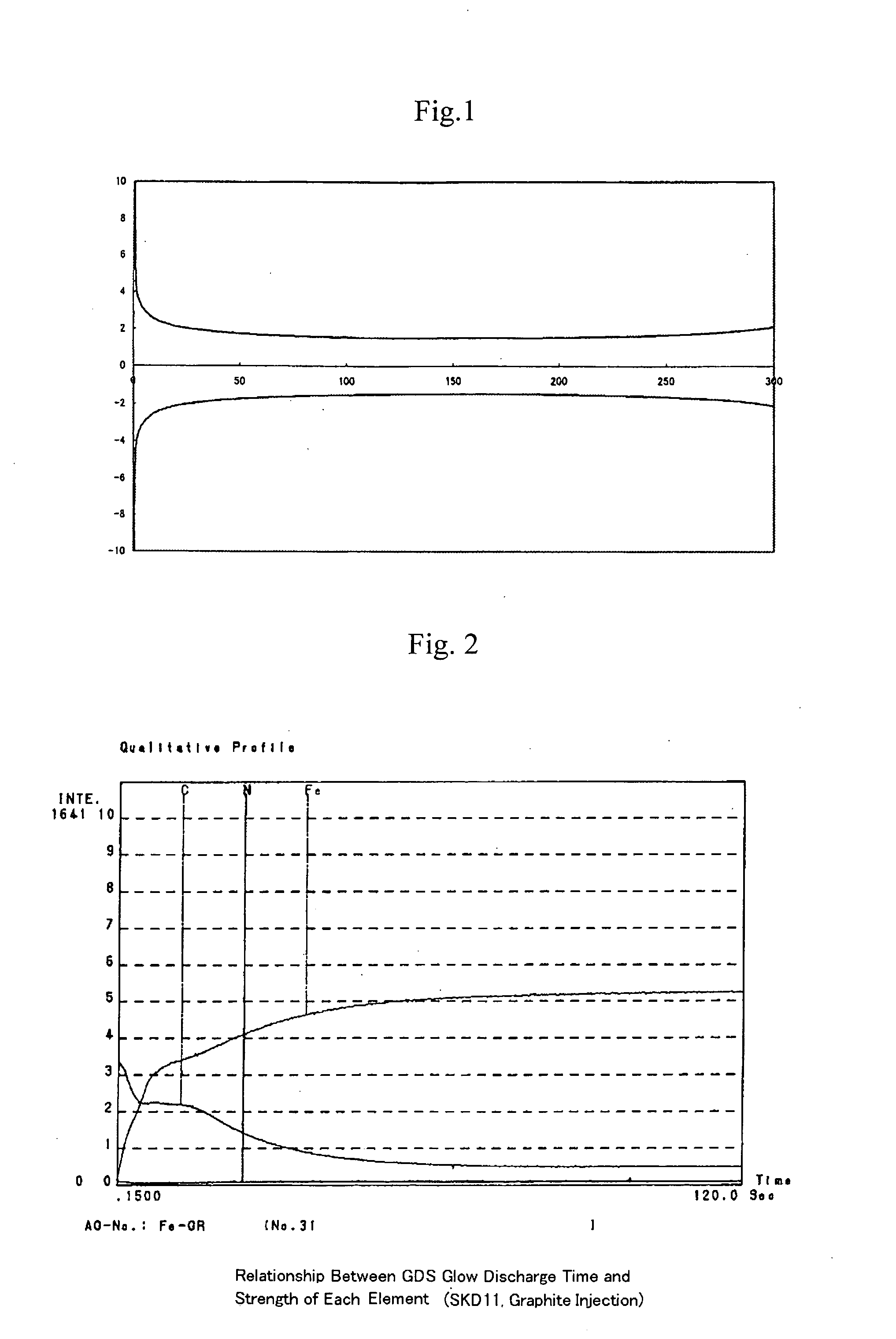
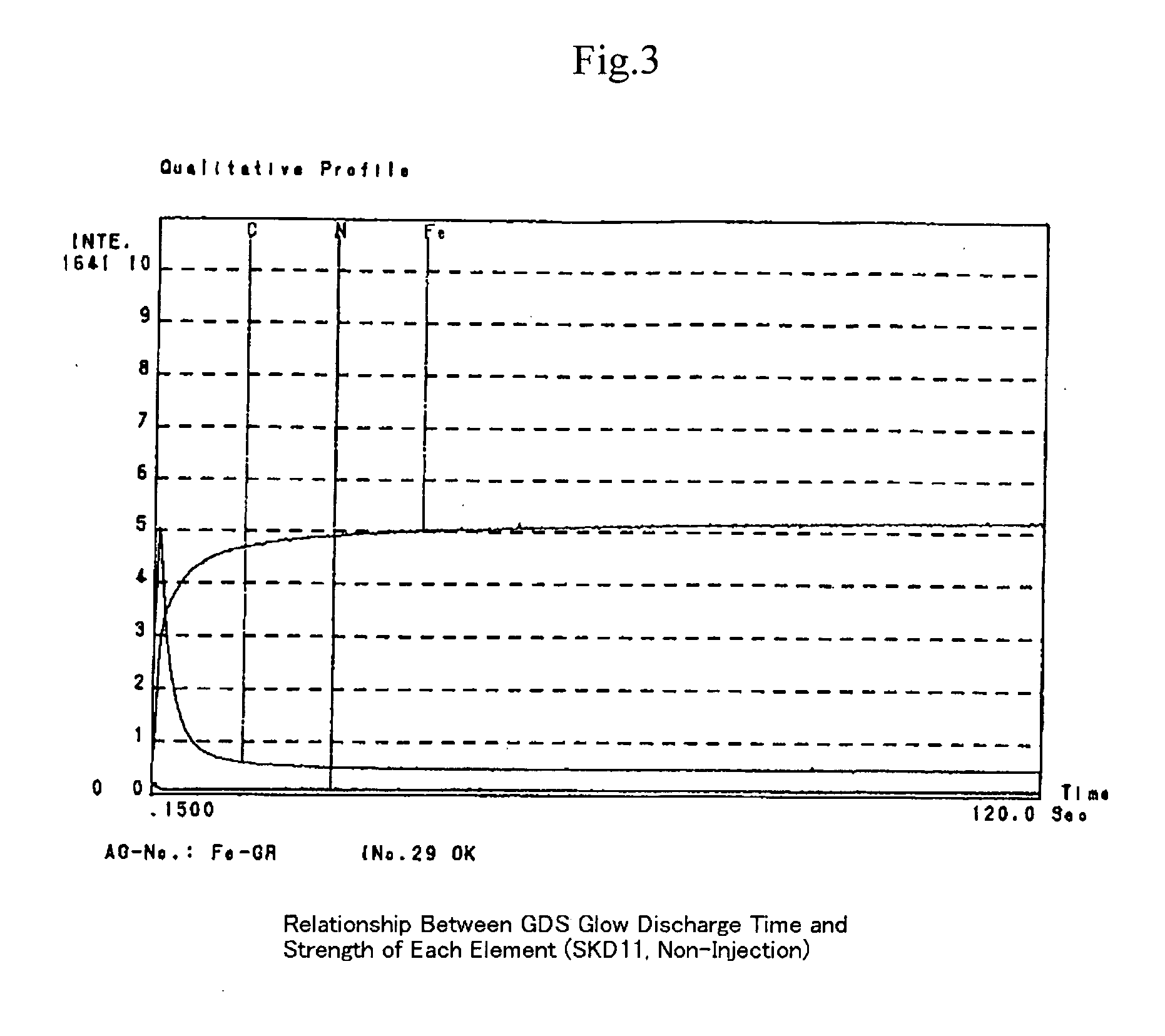
[0158] In the analysis result (FIG. 3) of the Comparative Example 2, the carbon components C are extremely reduced from the work piece top surface, and in the Embodiment 2 (FIG. 2), many carbon components are detected from the top surface to a certain depth, namely approximately 1.2 μm in the depth. Accordingly it is understood that in the Embodiment 2, a lubricant layer into which carbon components are properly penetrated is formed.

(2) SEM-EDX Analysis

[0159] By using a combination of a field emission scanning electronic microscope (FE-SEM) and an energy dispersive spectroscopic analysis (EDX), the surface analysis is performed repeatedly in the identical portion after the Ar ion sputtering treatment, to analyze distribution of the existing elements in the portion. As a work piece are used SKD11, SUJ2, and A7075.

[0160] S-4100 Vacc: 15 kV made by Hitachi Co., Ltd. is used as a field emission scanning electronic microscope (FE-SEM), and EDS2000 system made by IXRF SYSTEM as an ene...

Example

[0184]FIG. 14A shows a friction behavior view of the Comparative Example 3, FIGS. 14B and C show an optical microscopic photo of friction scars of the Comparative Example 3, and FIG. 14D shows a roughness curve of disc friction scars of the Comparative Example 3. The friction behavior fluctuated from the beginning of the friction and showed a friction coefficient of approximately 1.0. It was observed that from the state of the friction scars the ball was worn and the disc, as seen from the roughness curve, was swollen than the original surface due to transferring from the ball.

[0185] On the other hand, as seen from FIGS. 13A to 13D, the friction coefficient of the Embodiment 3 where the graphite was injected was maintained as the friction coefficient value of approximately 0.2 under the load of 4.9N to the friction frequency of approximately 3000 times.

[0186] When a sample was used in such a way that an injection distance of the graphite was 50 mm, other injection conditions were ...

Example

[0187] Next, with regard to the Embodiment 4 and the Comparative Example 4, a slip rate was set as 20 mm / sec and in the Comparative Example 4 a load was set as 0.49 N, and in the Embodiment 4 a load was set as 1.96 N. Under these conditions the friction experiment was performed.

[0188] In the Comparative Example 4, the friction coefficient showed equal to or more than 0.5 from the beginning of the friction and the friction fluctuation and the disc wear were large, and further, much adhesion on the ball from the disc existed. Accordingly the wear amount could not be measured (FIG. 16A to 16D).

[0189] In contrast, the Embodiment 4 maintains a friction coefficient value equal to or less than 0.2 until the number of frictions exceeds 2000 times under a load of 1.96 N and the roughness curve of the disc friction scars shows clearly that the roughness is smaller than that of the Comparative Example 4 (FIGS. 15A to 15D).

[0190] In addition, in the Embodiment 4, the wear amount of the ball ...


PUM

PropertyMeasurementUnit
Fractionaaaaaaaaaa
Pressureaaaaaaaaaa
Lengthaaaaaaaaaa

Abstract

A method enabling to form a lubricating layer on a work piece and a device to form the same in a simple blast processing are provided, in which injection materials can be injected at higher speed than the conventional way, thereby even a small specific gravity injection materials such as graphite and the like can be used for blast operation.
In an injection nozzle of a direct pressure type blast processing device which injects a mixture of injection materials and compressed gas, an aperture which is formed in an axial direction of the injection nozzle has such shape that meets the following conditional equations (1) and (2) in a cross section orthogonal to the axial direction at an arbitrary distance x away from the entrance of the injection nozzle. a=Gp1[2gκκ-11RT1{(pp1)2κ-(pp1)κ+1κ}]-12(1)pp1=1-(1-p2p1)(xL)(2)

Description

BACKGROUND OF THE INVENTION [0001] 1. Field of the Invention [0002] The present invention relates to an injection nozzle and a blast processing method which are suitable for injecting injection materials on a work piece at a high speed, a blast processing device with the injection nozzle, and a method of forming a lubricating layer on the surface of the work piece by the blast processing method. [0003] 2. Description of the Related Art [0004] Generally, a lubricating layer is formed on the surface of machine element components such as sliding products and the like which require frictional resistance and abrasion resistance so that a superior frictional resistance and an abrasion resistance can be provided over a prolonged period. As a method of forming such a lubricating layer, there is a method of applying liquid lubricants such as lubrication oil, grease or the like, on the surface. The effect of this method, however, is restricted by the working environment in such a way that the...

Claims


Application Information

Patent Timeline
IPC IPC(8): B24C5/02B24C1/00B24C5/04C23C24/04
CPCB24C1/00C23C24/04B24C5/04
Inventor UMEDA, KAZUNORIISHIWATA, MASATOTSUKITA, MORIOTSUKAMOTO, MIKIOTANAKA, AKIHIROHANADA, KOTARO
Owner FUJI MFG CO LTD
Learn More