
Subassembly of an electrical machine and electrical machine with one such subassembly

Inactive Publication Date: 2004-07-08
COMPACT DYNAMICS
View PDF4 Cites 2 Cited by
  • Summary
  • Abstract
  • Description
  • Claims
  • Application Information

AI Technical Summary

Benefits of technology

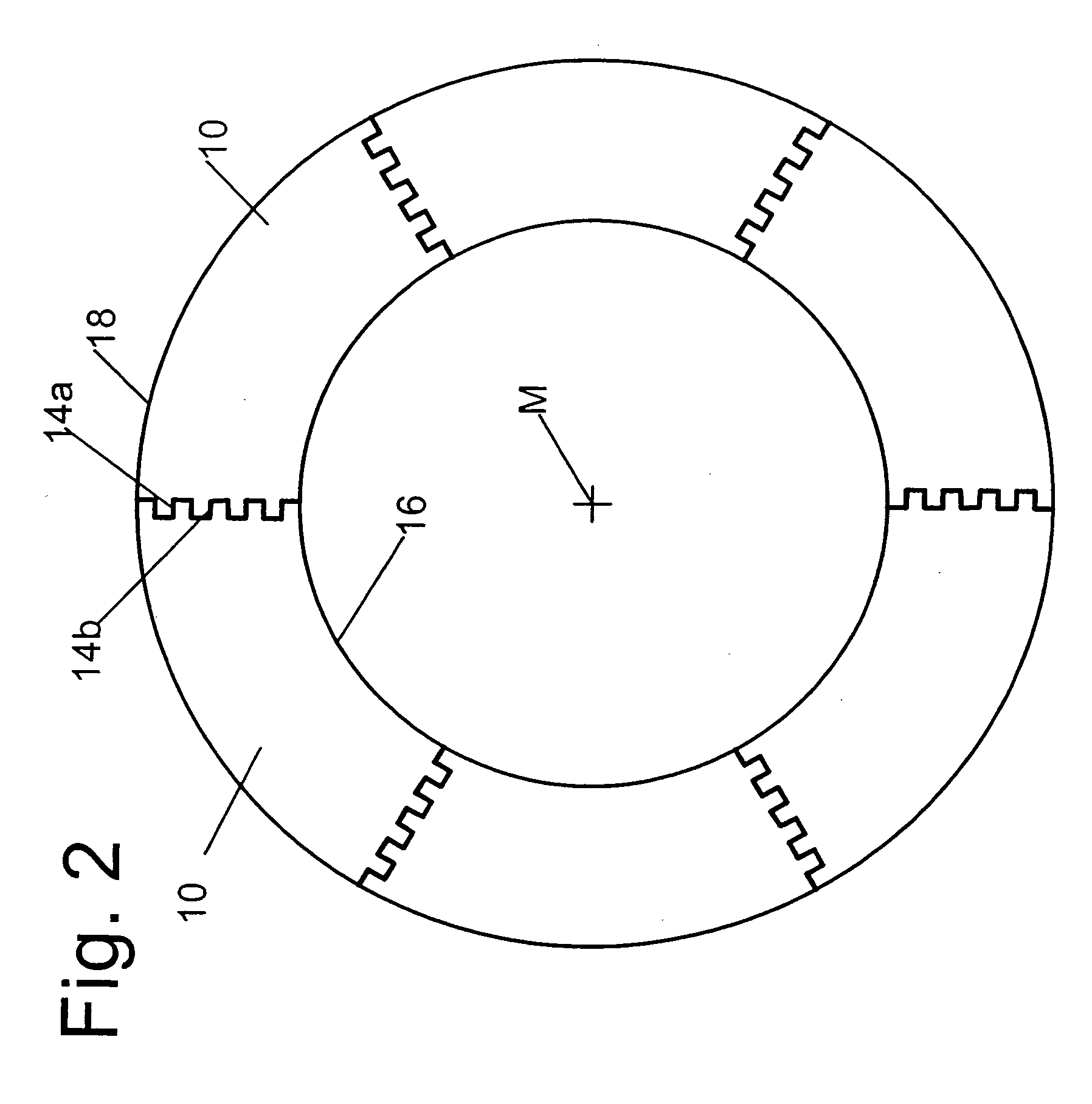
[0017] In a preferred embodiment of the invention, the connecting joint of the circular ring or circular disk-shaped sheet metal segments is oriented essentially radially. It is, however, also possible to provide the edges of the sheet metal segments which together form the connecting joint with such a structure that the sheet metal segments can be hooked or locked together. This, too, contributes to provide stability.

Problems solved by technology

If the individual sheet metal layers of the rotor or stator are manufactured as integral parts (so-called round plates), the punching scrap is considerable.
Rotors which are manufactured in this manner, however, have a limited maximum speed because their strength in the radial direction is not very high.
Correspondingly, the natural frequency of stators which are manufactured in this manner is relatively low which results in increased damping expenditures.

Method used


Image

  • Subassembly of an electrical machine and electrical machine with one such subassembly
  • Subassembly of an electrical machine and electrical machine with one such subassembly
  • Subassembly of an electrical machine and electrical machine with one such subassembly

Examples


Embodiment Construction

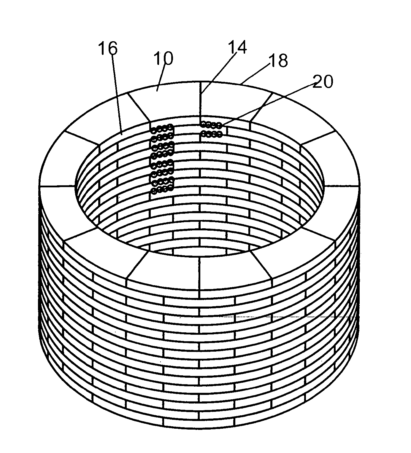
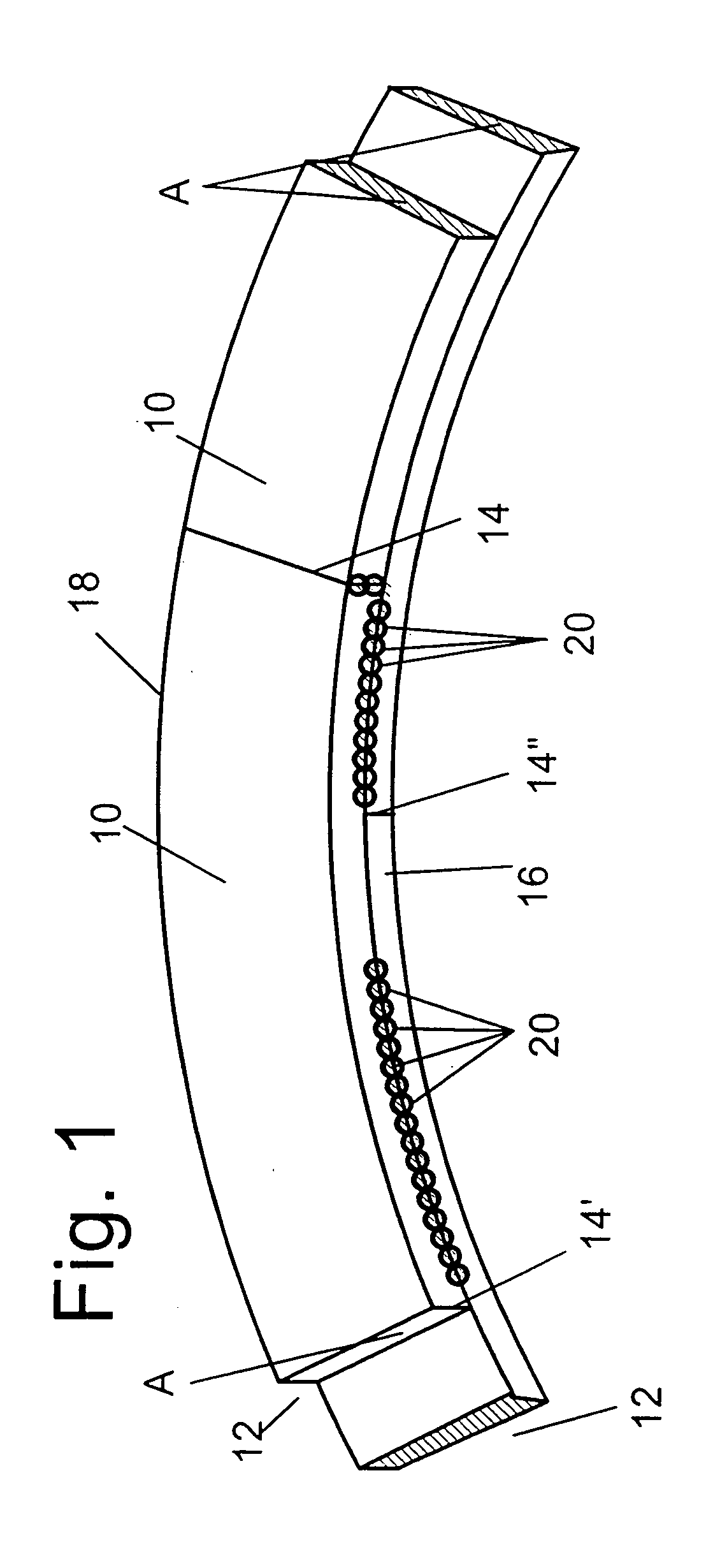
[0027] The section shown in FIG. 1 of an inventive assembly is a rotor of an external rotor machine, in which, however, for the sake of clarity the electric details (squirrel-cage winding etc.) are omitted. The assembly is formed from sheet metal segments 10. For the formation of one sheet metal layer 12 several circular ring segment-shaped sheet metal segments 10 are arranged adjacent to one another, with two sheet metal segments 10 each abutting at a connecting joint 14. A plurality of such sheet metal layers 12 stacked to the desired height results in the assembly.

[0028] The sheet metal segments 10 are concentrically arranged about a centre axis M (see FIG. 2) and have a predetermined minimum cross-sectional area A each in the radial direction (see FIG. 1) which influences the resistance against centrifugal forces. The sheet metal segments 10 of superposed sheet metal layers 12 overlap one another in the circumferential direction by approx. 25% in the shown example and are joined...


PUM


Abstract

The invention relates to an assembly of an electric machine with at least two abutting circular ring or circular disk-shaped sheet metal layers, wherein each of the sheet metal layers is formed by several circular ring or circular disk-shaped sheet metal segments which are arranged concentrically about a centre axis, of which two each are abutting under the formation of a connecting joint and comprise a predetermined minimum cross-sectional area in the radial direction, and with the sheet metal segments of abutting sheet metal layers partially overlapping one another in the circumferential direction and are joined by welds distributed along the circumferential area, with the number of welds between a connecting joint of two sheet metal segments of a sheet metal layer and a connecting joint of two sheet metal segments of a neighbouring sheet metal layer being calculated in such a manner that the sum of the effective areas of these welds is at least approximately equal to the predetermined minimum cross-sectional area of the sheet metal segments.

Description

[0001] The invention relates to an assembly of an electric machine as well as to an electric machine with such an assembly.DEFINITIONS[0002] The term "assembly of an electric machine" as used herein refers both to a stator and a rotor of an electric machine in the form of an internal or external rotor machine. An electric machine in this context may be an electric motor as well as an electric generator. The invention is applied, in particular, to rotary machines of all kinds (synchronous, asynchronous, reluctance, permanent field machines or the like).STATE OF THE ART[0003] In the state of the art it is known to build the magnetically conducting parts of a machine (in particular of an alternating current machine) of laminations because of the otherwise occurring eddy currents. For the core assemblies, typically single or double-sided insulated sheet panels of a thickness between 0.35 mm and 1.5 mm of dynamo sheet metal (hot rolled electric-quality sheet) are cut to correspondingly s...

Claims


Application Information

Patent Timeline
IPC IPC(8): H02K1/18H02K1/06H02K15/02
CPCH02K1/06H02K1/22
Inventor GRUNDL, ANDREASHOFFMAN, BERNHARD
Owner COMPACT DYNAMICS
Learn More