
Hose anti-collapse ribs, systems and methods

a technology of ribs and hoses, applied in the direction of hose connections, combustion-air/fuel-air treatment, intake silencers for fuel, etc., can solve the problems of high cost, difficult installation, heavy, movement can damage, or interfere with the operation of engine control sensors, etc., to achieve low cost, less flow restriction, and minimal cross-sectional area

Active Publication Date: 2018-02-13
THE GATES CORP
View PDF12 Cites 0 Cited by
  • Summary
  • Abstract
  • Description
  • Claims
  • Application Information

AI Technical Summary

Benefits of technology

[0006]The present invention is directed to hose anti-collapse ribs, systems and methods which provide resistance to collapse in turbocharger intake hoses and other vacuum hose applications. In particular, embodiments of the present invention are directed to an internally disposed stiffening rib that expands and locks into place on the hose ID. This solution allows relatively inexpensive, thinner wall hose to be used in relatively higher vacuum applications. The rib may be made of relatively thin, low cost molded plastic. The material might be selected to be resistant to rusting, and resistant to other chemicals which could include ethylene glycol, re-circulated fuel, oil, etc. Advantageously, such ribs cause less flow restriction than a typical internal spring. Unlike springs, the ribs expand and preferably lock into the hose. The present ribs also have minimal cross-sectional area exposed to the flow stream within a hose, minimizing the force that the flowing fluid applies, further assuring that the rib will stay in place.
[0011]In operation, a hose anti-collapse rib such as described above may be deployed by disposing the hose anti-collapse rib within a hose that is to be subject to vacuum or similar collapsive forces and expanding opposite curved cantilevered portions of the rib to form the rib into a generally circular shape in contact with an inner surface of the hose. This expanding may be accomplished in certain embodiments by indexing a ridge defined in an outer surface of one tab in a groove defined in an inner surface of the other tab. More specifically, the expanding may include sliding the ridge defined in the outside surface of the one tab in a groove defined in an inside surface of the other cantilevered portion, guiding the ridge into the groove defined in the inner surface of the other tab. Preferably the hose anti-collapse rib is locked in the generally circular shape. Such locking may, in accordance with certain embodiments of the present invention, include mating a first tab defined by an end of a first of the cantilevered portions with a second tab defined by an end of a second of the cantilevered portions. Movement of the rib within the hose may be prevented by engaging an interior surface of the hose with a ridge defined in an outer surface of the rib.
[0015]An embodiment of a method for deploying such a rib might again include disposing the hose anti-collapse rib within a hose subject to vacuum, expanding the opposite curved cantilevered portions of the rib to form the rib into the generally circular shape in contact with an inner surface of the hose, and indexing the raised button defined by one of the tabs in a button receptive orifice defined in the other of the tabs to lock the hose anti-collapse rib in the generally circular shape. The expansion of the rib might be facilitated by sliding the raised button in a slot defined in a surface of the other of the cantilevered portions, guiding the button into the orifice defined in the other tab.

Problems solved by technology

These solutions are expensive, difficult to install, and heavy.
Because internal springs have a high surface area and have no interference fit with the hose, vibration and high air flow can cause them to move out of place, even into the engine, possibly even into the intake port.
Even minimal spring movement can damage, or interfere with the operation of, engine control sensors.
Regardless, movement of such a spring could result in hose collapse.
Furthermore, built-in springs often require hand lay-up manufacturing.
Disposition of springs within hose can cause discontinuities that may lead to premature hose failure.
Such discontinuities might include: voids in hoses in which springs are molded-in; shear stress in the rubber of the hose due to the great difference in stiffness between the spring and the hose rubber; uneven loading of clamps due to an underlying spring; and / or vibration failures due to the spring wearing through the rubber of the hose.

Method used


Image

  • Hose anti-collapse ribs, systems and methods
  • Hose anti-collapse ribs, systems and methods
  • Hose anti-collapse ribs, systems and methods

Examples


Embodiment Construction

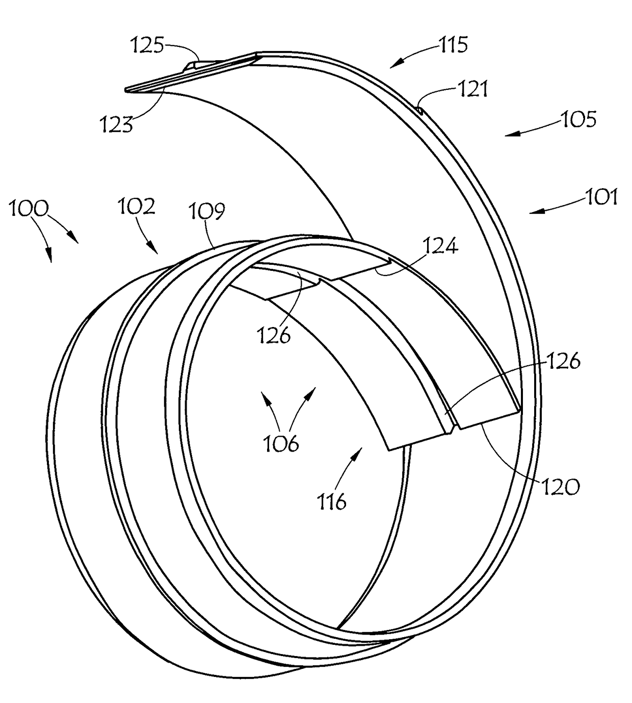
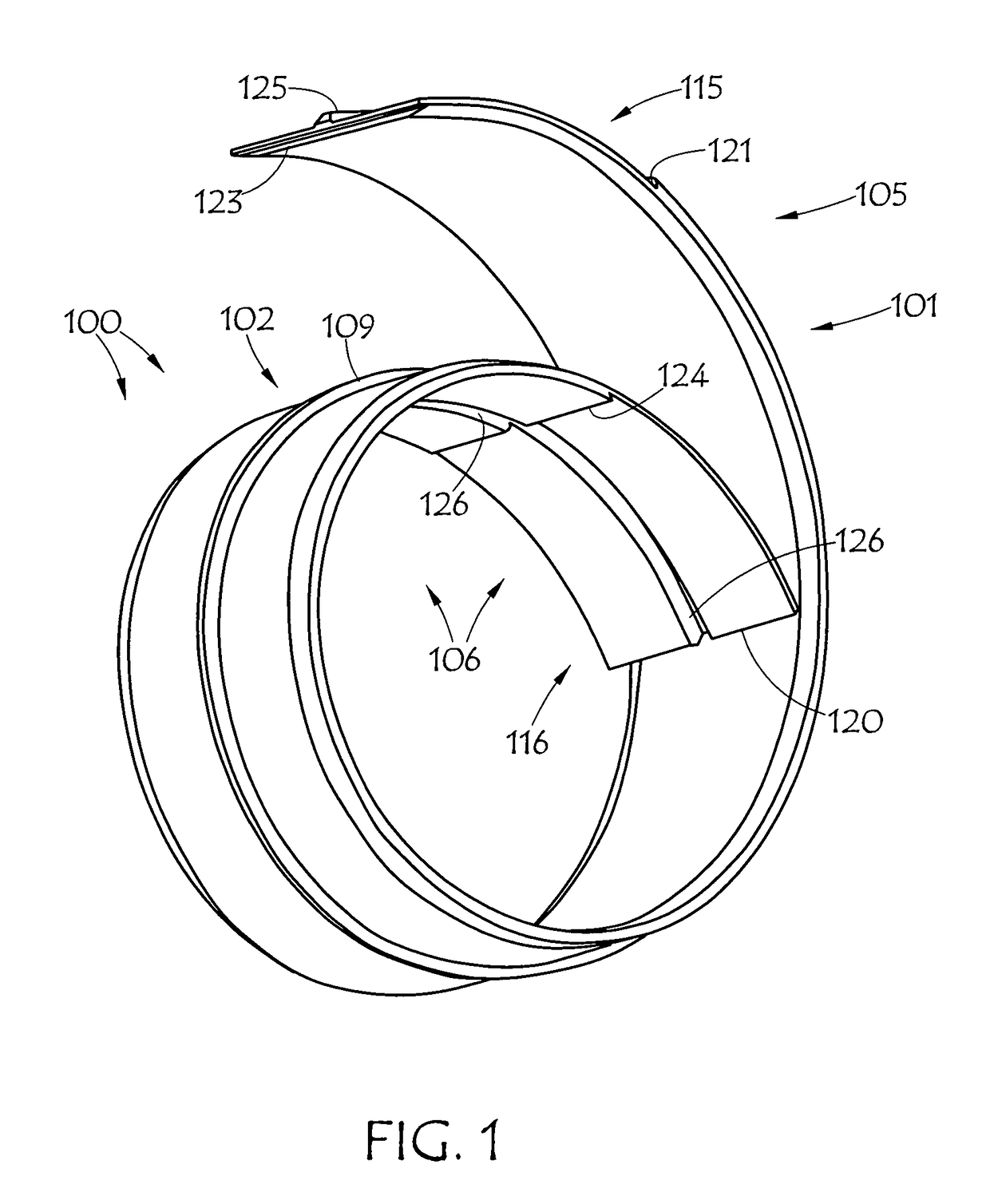
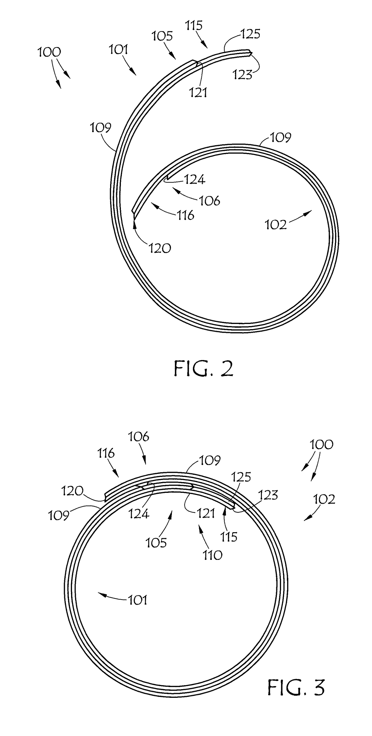
[0031]Embodiments of present hose anti-collapse rib 100 preferably employ a dual cantilever limb configuration, where the rib is molded in the approximate shape of two integral limbs one with a curvature greater than the other, deflected or curved in opposite, facing directions. This provides a non-circular, somewhat spiral, rib, such as illustrated in FIGS. 1 and 2, having the general shape of a “6” or a “9”. If first limb 101 is thereafter positioned under limb 102 the generally circular, spiral, collapsed ring configuration shown in FIG. 3 is obtained. Upon expansion of rib 100, the expanded and locked (more) circular shape shown in FIG. 4 is obtained.

[0032]In greater detail, the illustrated embodiment of an integral hose anti-collapse rib 100 might be a unitary body having a first cantilevered portion or limb 101. First limb 101 is preferably curved and defines a first end 105. A second cantilevered portion or limb 102 is preferably curved in a direction opposite the direction o...


PUM

PropertyMeasurementUnit
curvatureaaaaaaaaaa
thicknessaaaaaaaaaa
flexibleaaaaaaaaaa

Abstract

An integral hose anti-collapse rib comprises a unitary body having a first cantilevered portion curved in a first direction. This first cantilevered portion defines a first end. A second cantilevered portion is curved in a direction opposite the direction of the first cantilevered portion, in a direction facing the first cantilevered portion. The second cantilevered portion also defines a second end disposed at an opposite extent of the rib from the first end. The hose anti-collapse rib also comprises a locking mechanism that locks the first end of the rib to the second end of the rib, such that the first and second cantilevered portions together form a generally circular shape. Embodiments of locking mechanisms may include a button and orifice locking mechanism and / or a tab and channel locking mechanism. In a relaxed state in which the locking mechanism is not engaged, the rib preferably defines a non-circular, generally spiral shape.

Description

CROSS-REFERENCE TO RELATED APPLICATIONS[0001]This is a continuation-in-part of U.S. patent application Ser. No. 12 / 072,343, filed Feb. 26, 2008, entitled Hose Anti-collapse Ribs, Systems and Methods, which is hereby incorporated herein by reference.BACKGROUND OF THE INVENTION[0002]Field of the Invention[0003]This invention relates generally to hoses, more particularly to hoses subject to vacuum, and specifically to hose anti-collapse rib systems and methods.[0004]Description of the Prior Art[0005]Turbocharger intake hoses and other applications that require vacuum resistance typically require thick walls, stiff materials, built-in springs, or internal springs to resist collapse. These solutions are expensive, difficult to install, and heavy. Because internal springs have a high surface area and have no interference fit with the hose, vibration and high air flow can cause them to move out of place, even into the engine, possibly even into the intake port. Even minimal spring movement...

Claims


Application Information

Patent Timeline
Patent Type & Authority Patents(United States)
IPC IPC(8): F16L11/10F02M35/12F16L33/213F02M35/10
CPCF16L11/10F02M35/10091F16L33/213F02M35/1277Y10T29/49
Inventor SCHELHAAS, DOUGLAS D.GILBREATH, DONALD R.SAUPE, TIM
Owner THE GATES CORP
Learn More