Magneto-optical recording medium and magneto-optical storage device

Inactive Publication Date: 2005-06-16
FUJITSU LTD
View PDF14 Cites 8 Cited by
  • Summary
  • Abstract
  • Description
  • Claims
  • Application Information

AI Technical Summary

Benefits of technology

[0012] It is an object of the present invention to provide a magneto-optical recording medium capable of stably reproducing both ROM information and RAM information when the ROM information and the RAM information are to be simultaneously read.
[0013] Another object of the present invention is to provide a magneto-optical recording medium capable of improving ROM signal jitter and magneto-optical (MO) signal jitter in a ROM area when ROM information and RAM information are to be simultaneously read.
[0014] Still another object of the present invention is to provide a magneto-optical storage device capable of improving ROM signal jitter and magneto-optical (MO) signal jitter in a ROM area when ROM information and RAM information are to be simultaneously read.

Problems solved by technology

There are many problems encountered in simultaneously reproducing ROM information recorded in the form of phase pits PP and RAM information recorded in the form of magneto-optical recording spots OMM from an optical recording medium, which has the ROM information and the RAM information on one recording surface.
First, the optical intensity modulation caused in reading the ROM information is responsible for noise produced in reproducing the RAM information when the ROM information and the RAM information are to be stably reproduced.
However, the attempt is not effective enough to reduce the noise if the optical intensity modulation of the ROM information is large.
It is also difficult to control the laser beam intensity at a high speed with the feedback control loop.

Method used


Image

  • Magneto-optical recording medium and magneto-optical storage device
  • Magneto-optical recording medium and magneto-optical storage device
  • Magneto-optical recording medium and magneto-optical storage device

Examples


Embodiment Construction

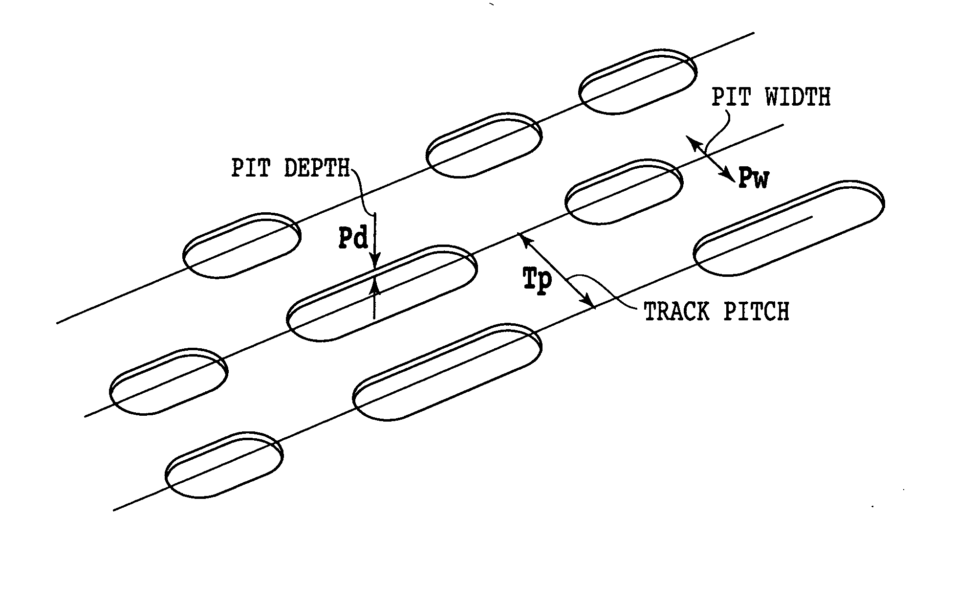
[0045]FIG. 6 shows a layout of phase pits, which serve as a premise for understanding the features of a magneto-optical recording medium according to the present invention. In FIG. 6, each of the phase pits has a depth Pd, i.e., an optical depth. A track pitch Tp represents the radial distance between phase pits, and a pit width Pw represents the radial width of each phase pit. In an experiment described below, a polycarbonate substrate having a track pitch Tp of 1.6 μm, a pit width Pw of 0.40 μm, a minimum pit length of 0.8 μm, and a pit depth Pd of 40 nm was prepared. At this time, a plurality of substrates having differently adjusted angles θ1 of edges of pits 32 (see FIG. 7), each formed to a depth of about 40 nm in a substrate 30, were prepared by controlling the film thicknesses of photoresists applied to stampers in a stamper production process and applying ultraviolet rays to the substrates.

[0046] Specifically, the phase pits 32 had several random lengths at certain interva...


PUM


Abstract

A magneto-optical recording medium has a substrate having a ROM area with a plurality of phase pits defined therein as providing a ROM signal, and a magneto-optical recording film deposited in an area of said substrate which corresponds to said ROM area, for recording a RAM signal. The phase pits have edges having an average angle of inclination ranging from 10° to 40° at a position in a range of one-half of the depth of each of the phase pits ±20%. Each of said phase pits has a width ranging from 300 nm to 500 nm, and is modulated by a modulation factor ranging from 10% to 30%.

Description

[0001] This is a continuation of PCT International Application NO. PCT / JP02 / 13085, filed Dec. 13, 2002, which was not published in English.BACKGROUND OF THE INVENTION [0002] 1. Field of the Invention [0003] The present invention relates generally to a magneto-optical recording medium, and more particularly to a magneto-optical recording medium capable of simultaneously reproducing ROM / RAM information. [0004] 2. Description of the Related Art [0005]FIG. 1 of the accompanying drawings is a plan view of an example of a conventional magneto-optical disk according the ISO standards. The magneto-optical disk has a lead-in area 2 and a lead-out area 4. The lead-in and -out areas 2 and 4 store ROM information representative of usage of the disk, etc. in the form of phase pits that are formed by lands and grooves on a. polycarbonate substrate. The depth of the phase pits representing the ROM information is set to maximize the optical intensity modulation upon reproduction of the information....

Claims


Application Information

Patent Timeline
IPC IPC(8): G11B7/007G11B7/24G11B7/26G11B11/105
CPCG11B7/0079G11B7/24038G11B7/26G11B11/10597G11B11/10578G11B11/10582G11B11/10584G11B11/10543
Inventor HOSOKAWA, TETSUOAOYAMA, NOBUHIDE
Owner FUJITSU LTD
Why Eureka
Try Eureka