Disk clamping mechanism and disk drive system

a technology of clamping mechanism and disk drive, which is applied in the direction of magnetic recording, data recording, instruments, etc., can solve the problems of difficult to make the disk drive system thinner, difficult to stably rotate the thin optical disk clamped between the turntable and the clamper,

Inactive Publication Date: 2011-03-24
RICOH KK +1
View PDF14 Cites 2 Cited by
  • Summary
  • Abstract
  • Description
  • Claims
  • Application Information

AI Technical Summary

Benefits of technology

[0015]According to another embodiment, there is provided a disk drive system including the above disk clamping mechanism, where when the rotation of the flexible thin optical disk is stabilized, the flexible thin optical disk is moved closer to the stabilizer member to suppress the run-out of the flexible thin optical disk such that recording or reproducing of information is stably carried out on the flexible thin optical disk.

Problems solved by technology

With the related art configuration, it is possible to clamp a thin-film shaped optical disk having a thickness of 0.3 mm or less (hereinafter called a “thin optical disk”) between the turntable and the clamper; however, it may be difficult to stably rotate the thin optical disk clamped between the turntable and the clamper.
Accordingly, the configuration of the disk drive system for the thin optical disk may become complex and thus it may be difficult to make the disk drive system thinner.
Further, there may not so far have been proposed a disk drive system in which the thin optical disk is loaded or unloaded with a tray and the tray is provided with a stabilizer for stably rotating the thin optical disk.

Method used


Image

  • Disk clamping mechanism and disk drive system
  • Disk clamping mechanism and disk drive system
  • Disk clamping mechanism and disk drive system

Examples


Embodiment Construction

[0035]In the following, preferred embodiments of the present invention will be described with reference to the accompanying drawings.

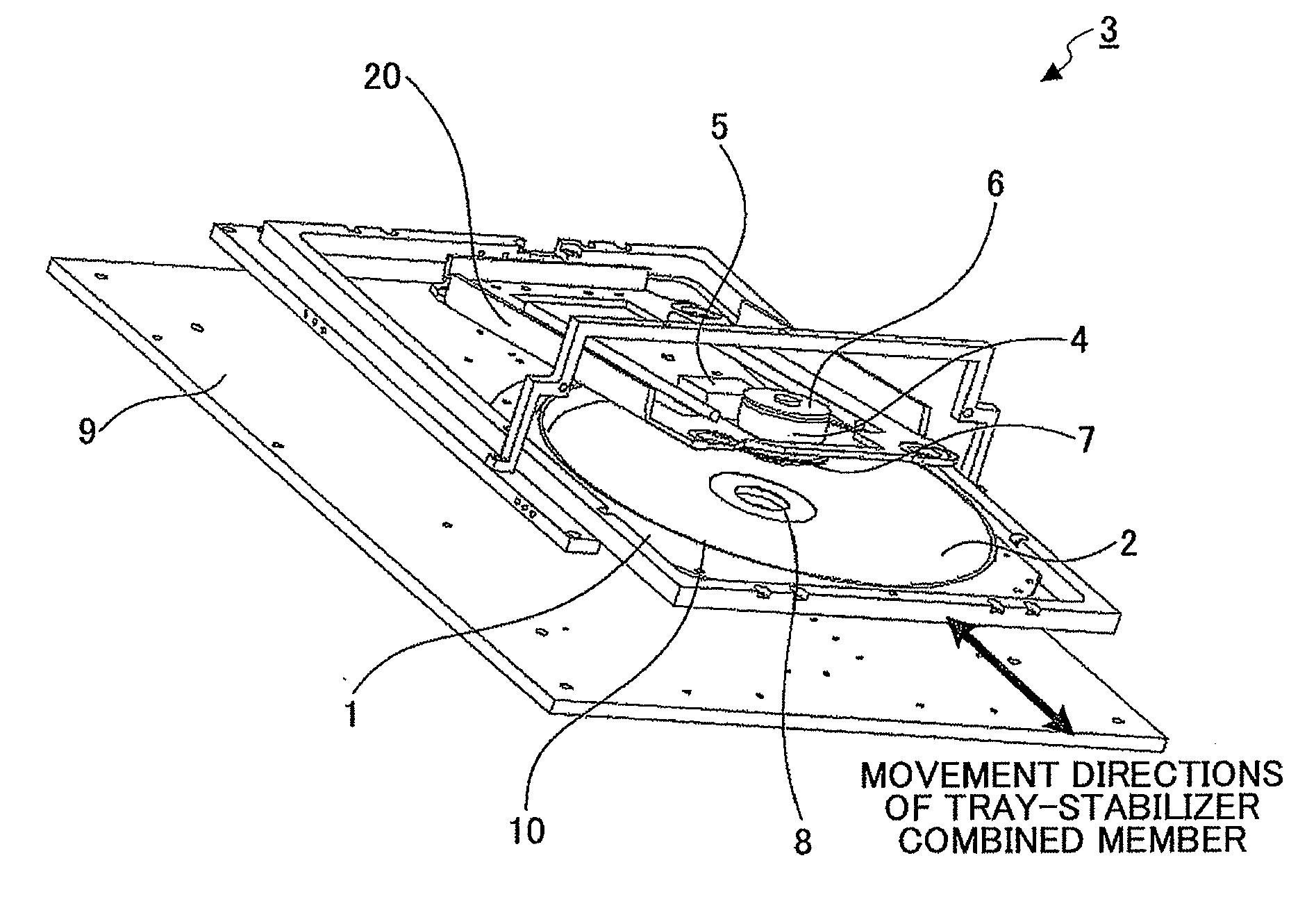
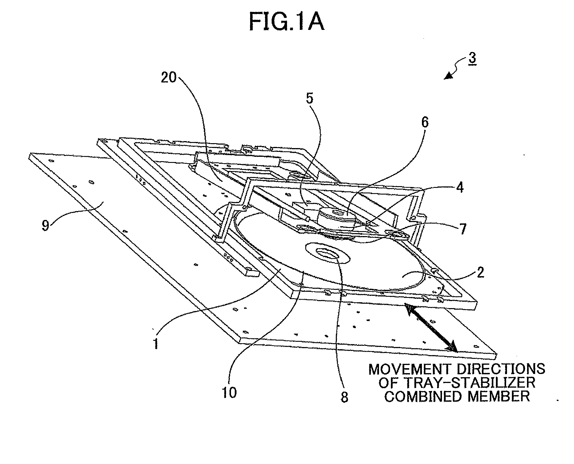
[0036]FIG. 1A is a schematic perspective view illustrating a configuration of the disk drive system 3 according to an embodiment. As illustrated in FIG. 1A, a disk drive system 3 loads a thin optical disk 2 inside a case 9 and unloads outside the case 9 by moving a tray-stabilizer combined member 1 in directions indicated by a bidirectional arrow that illustrates movements of the tray-stabilizer combined member 1. A spindle unit 4 configured to rotate the thin optical disk 2 includes a spindle motor 6 and a turntable 7. A clamper 8 is rotationally connected and supported on the tray-stabilizer combined member 1 with a sufficient space by a not-shown supporting member formed of an elastic member.

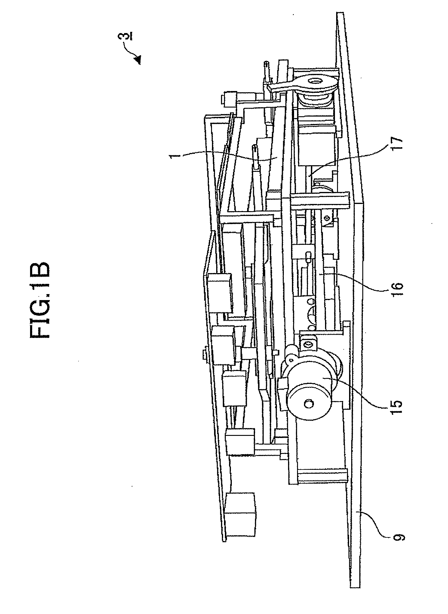
[0037]FIGS. 1B and 1C illustrate a drive system of the disk drive system 3 respectively viewed from left and right sides of the drive system by which the tray-s...


PUM

PropertyMeasurementUnit
thicknessaaaaaaaaaa
distanceaaaaaaaaaa
lengthaaaaaaaaaa

Abstract

A disclosed disk clamping mechanism includes a turntable fixed on a rotational shaft of a spindle motor to rotate a flexible thin optical disk, a stabilizer member configured to suppress a run-out of the flexible thin optical disk by an applying aerodynamic force to the rotating flexible thin optical disk so as to stabilize the run-out of the rotating flexible thin optical disk, and a clamper movably supported in a center of the stabilizer member in a direction perpendicular to a surface of the flexible thin optical disk. In the disclosed disk clamping mechanism, the flexible thin optical disk is sandwiched between the turntable and the clamper such that the turntable and the clamper rotate the flexible thin optical member sandwiched in-between.

Description

BACKGROUND OF THE INVENTION[0001]1. Field of the Invention[0002]The invention generally relates to a disk drive system and a clamping mechanism for use in a recording-reproducing apparatus for recording or reproducing information. More specifically, the invention relates to a disk drive system and a clamping mechanism capable of applying an aerodynamic force to a rotating flexible thin optical disk using a stabilizer to suppress a surface run-out of the flexible thin optical disk while rotating the flexible thin optical disk and stabilize the surface run-out of the rotating flexible thin optical disk.[0003]2. Description of the Related Art[0004]A related-art recording-reproducing apparatus for an optical disk generally includes a spindle motor having a shaft and a turntable fixed on the shaft. In the related-art recording-reproducing apparatus, the optical disk placed on the turntable is rotated while recording information on the optical disk or retrieving the information from the o...

Claims


Application Information

Patent Timeline
Patent Type & Authority Applications(United States)
IPC IPC(8): G11B17/028
CPCG11B17/0284G11B17/32G11B17/056
Inventor ONAGI, NOBUAKIAMAN, YASUTOMOTOKUMARU, HARUKITAKANO, YOSHIMICHIKOIDE, DAIICHIKAJIYAMA, TAKESHINISHIDA, MASAMI
Owner RICOH KK
Why Eureka
Try Eureka