Eureka AIR delivers breakthrough ideas for toughest innovation challenges, trusted by R&D personnel around the world.

Spark plug

a spark plug and spark plug technology, applied in spark plugs, spark plugs, basic electric elements, etc., can solve the problems of spark plug core nose self-destruct by explosion, spark plug core nose explosion, spark plug core explosion, etc., and achieve the effect of reducing fuel consumption and increasing horsepower

Inactive Publication Date: 2005-06-16
LINDSAY MAURICE E
View PDF26 Cites 16 Cited by
  • Summary
  • Abstract
  • Description
  • Claims
  • Application Information

AI Technical Summary

Benefits of technology

[0012] The present invention resides in a spark plug which produces greater horsepower than prior spark plugs while decreasing fuel consumption. The spark plug also prevents fouling, or the build-up of carbon and oil deposits on the core nose of the spark plug. The novel spark plug of the present invention is designed to achieve these objectives while operating in more modern cars which supply the spark plugs with a limited amount of electrical energy.
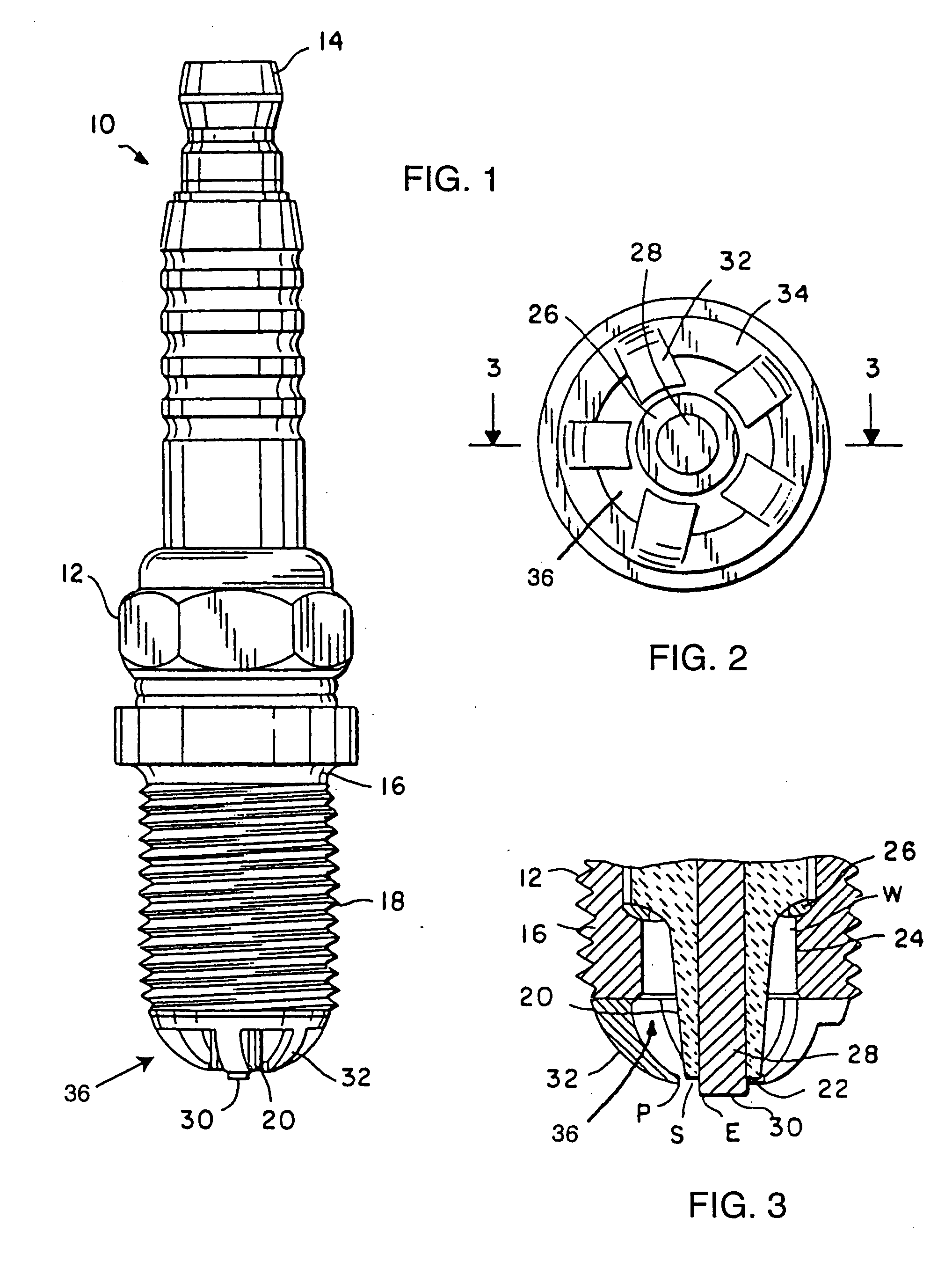
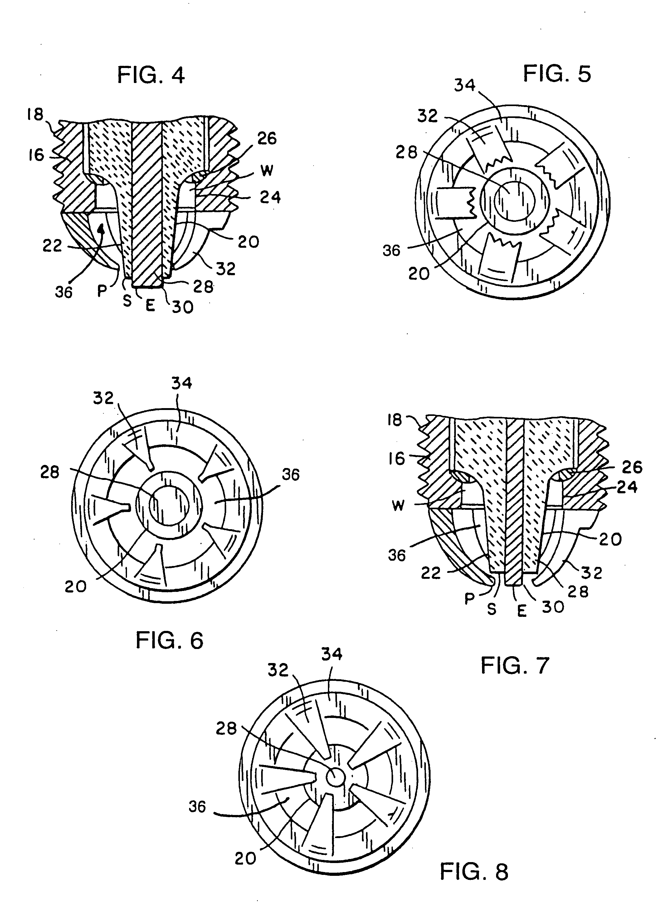
[0018] In a particularly preferred embodiment, a relatively unique result of the placement, spacing and material properties of the base, insulator, central electrode, and ground prongs is that instead of the spark jumping from the central electrode directly to the ground prong, the spark instead selects the path of least electrical resistance from the central electrode to the insulator and then crosses an air gap between the insulator and the ground prong end. This phenomenon is described as surface and air gap spark travel. The result of this phenomenon with the placement of one or more ground prongs about the insulator allows the spark to ionize any accumulation of carbon and oil surface deposits on the insulator while allowing multiple spark presentations. Another result of the design of the spark plug is that the energy requirements for the spark plug do not increase linearly with increased combustion chamber pressures as in conventional spark plugs.

Problems solved by technology

This is referred to as spark plug fouling which causes incomplete burning of the air / fuel mixture, possibly to a point of non-ignition.
The core nose may begin to glow above 850° C., potentially causing the spark plug core nose to self-destruct by explosion.
Aside from the loss of the spark plug, other internal components of the engine can also be severely damaged by a glowing spark plug.
Any accumulations of oil or carbon not located directly in the path of spark firing, such as those deposits on the insulator surface, will remain adhered and adversely affect the use of the spark plug.
However, the ignition systems of newer vehicles produce less energy than earlier systems and it has been found that the design of the surface to air gap spark plug of the '557 patent rarely operates very well in these newer systems.
Therefore, the spark plugs of both chambers fire resulting in the compression stroke chamber being ignited and the waste of a spark on the exhaust stroke chamber.
The energy requirements of the spark plug of the '557 patent have been found to be too great to run on such systems.

Method used


Image

  • Spark plug
  • Spark plug
  • Spark plug

Examples


Embodiment Construction

[0029] As shown in the drawings for purposes of illustration, the present invention is concerned with a spark plug, generally referred to in the drawings by the reference number 10. As illustrated in FIGS. 1-3, the spark plug 10 has an outer elongated tubular housing 12 having an upper end which is formed into a terminal 14. This terminal 12 is electrically connected to the ignition system of the engine which supplies the electrical energy to power or fire the spark plug 10. At the opposite end of the spark plug 10 is formed a base shell 16. A portion of the exterior surface of the housing 12, typically adjacent the base shell 16, includes a series of screw threads 18. The purpose of the screw threads 18 is to facilitate mounting the spark plug 10 within a receiving hole of an engine which accesses a combustion chamber.

[0030] Mounted within the tubular housing 12 is an insulator 20. The insulator 20 typically comprises a non-conductive and heat resistant material, such as porcelain...


PUM


Abstract

A spark plug having a fire hole at least partially comprised of or coated with a material, such as platinum, adapted to create a plasma of fuel and air to increase burn efficiency. At least a portion of the internal side-wall of a base shell of the spark plug is comprised of or coated with platinum material. Preferably, all exposed conductive portions within the combustion chamber are coated with or comprise of platinum material. Electrical resistence of the spark plug may also be selected so that the generated spark will travel from the center electrode from the surface of an insulator and fill an air gap to the end of a ground prong so as to effectively clean the insulator of surface deposits.

Description

RELATED APPLICATION [0001] This application is a continuation-in-part application of U.S. application Ser. No. 10 / 645,271, filed Aug. 20, 2003.BACKGROUND OF THE INVENTION [0002] The present invention relates to spark plugs. More particularly, the present invention relates to a spark plug for an internal combustion engine which includes a catalytic coating on a fire hole thereof to enhance combustion. [0003] Spark plugs are used in most internal combustion engines to provide high voltage sparks which ignite an air and fuel mixture within combustion chambers of an engine. During operation, a spark generating system delivers a pulse of electrical energy in the form of a high voltage to the terminal of the spark plug at timed intervals which are intended to coincide with combustion chamber piston placement. The spark plug directs the high voltage energy to jump or spark between a center electrode and a ground electrode of the spark plug. As the spark travels across the air gap of the ce...

Claims


Application Information

Patent Timeline
Patent Type & Authority Applications(United States)
IPC IPC(8): H01T13/46
CPCH01T13/39H01T13/50H01T13/467
Inventor LINDSAY, MAURICE E.
Owner LINDSAY MAURICE E
Why Eureka
Eureka Blog
Learn More