Sound insulating system
a sound insulation and system technology, applied in the direction of shock absorbers, mechanical equipment, transportation and packaging, etc., can solve the problems of reducing the overall weight of the vehicle, limiting the noise of the interior vehicle, and dominated the overall vehicle noise of the engin
- Summary
- Abstract
- Description
- Claims
- Application Information
AI Technical Summary
Benefits of technology
Problems solved by technology
Method used
Image
Examples
example a
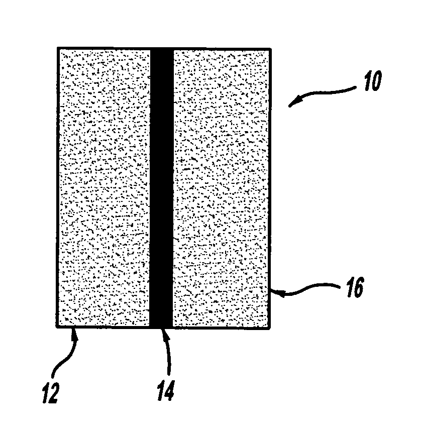
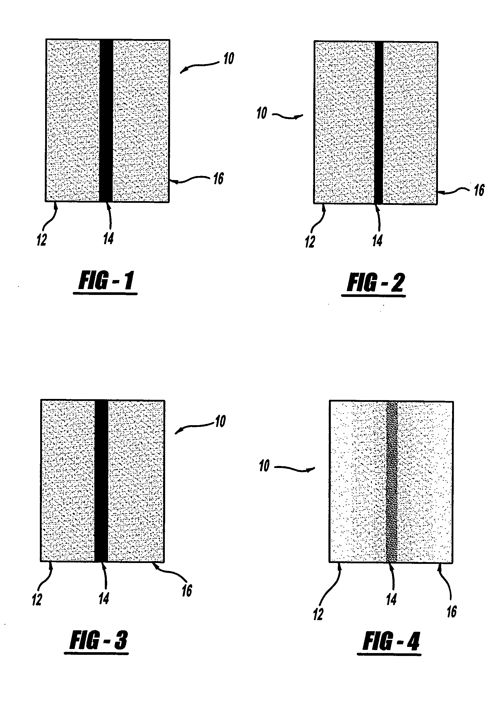
[0068] The absorber-barrier-absorber dash insulator or system 10 was made using viscoelastic foams as the absorbing layers 12, 16 and polyethylene sheet as the barrier layer 14.
[0069] Three-layer samples with dimensions 0.69 m×0.69 m×27 mm thick were made using 2 layers of Dow Developmental viscoelastic polyurethane foam #76-16-10-HW with a thickness of 13 mm, and a 0.36 mm thick polyethylene sheet as the middle barrier layer. The areal density of the sample was calculated by measuring the mass of the sample and dividing by the area of the sample. The areal density is shown in FIG. 14. The sample was placed over a 0.8 mm thick steel plate, and the assembly was inserted into the wall between the reverberation chamber and the semi-anechoic chamber. Noise was generated in the reverberation room using a speaker, and the sound pressure level was measured using four microphones placed at a distance of 1.17 m from the steel plate. An array of twelve microphones was placed in the semi-anec...
example b
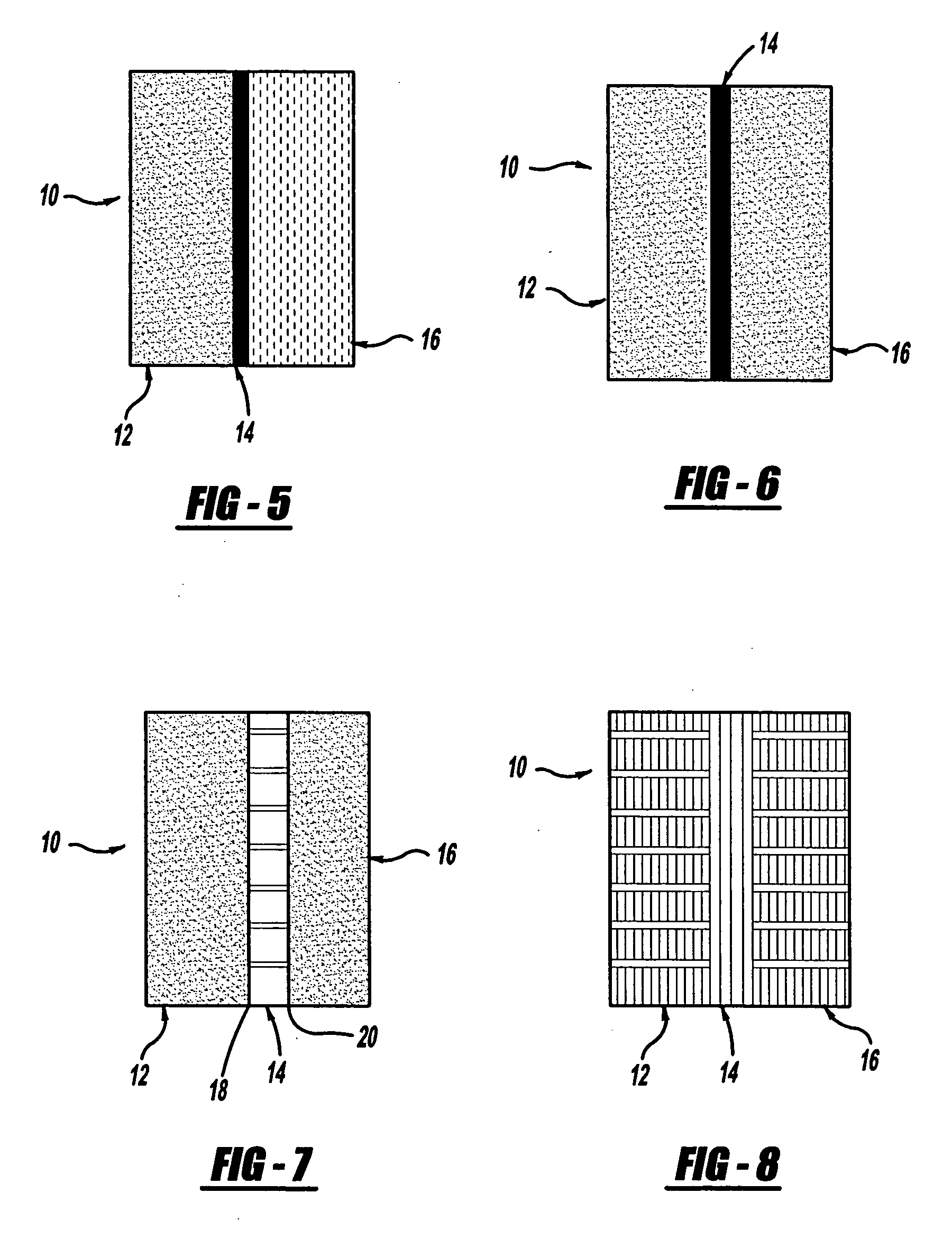
[0075] The absorber-barrier-absorber dash insulator or system 10 was made with viscoelastic foam as the first absorbing layer 12 against the sheet metal, 0.36 mm polyethylene sheet as the barrier layer 14 and a polymer fiber mat as the second absorber layer 16.
[0076] Three-layer samples with dimensions 0.69 m×0.69 m×32 mm thick were made using 1 layer of Dow Developmental viscoelastic foam #76-16-10-HW with a thickness of 13 mm, one layer of Owens Corning VERSAMAT (Sample 506R4800) fiber material with a thickness of 18 mm, and a 0.4 mm thick polyethylene sheet as the barrier layer 14. The areal density of the sample was calculated by measuring the mass of the sample and dividing by the area of the sample. The areal density is shown in FIG. 14. The noise reduction was measured using the method described in Example A with the viscoelastic foam against the steel plate. The results are shown in FIG. 10.
[0077] The normal incidence sound absorption of this sample was measured using Impe...
example c
[0078] The absorber-barrier-absorber dash insulator or system 10 was made using skinned, open cell polyurethane foam Grade ES-50 from E-A-R Specialty Composites (Indianapolis, Ind.) as the absorbing layers 12, 16 and a polypropylene honeycomb sheet from Plascore (Zeeland, Mich.) as the barrier layer 14.
[0079] Three-layer samples with dimensions 0.69 m×0.69 m×30 mm thick were made using two layers 12, 16 of E-A-R foam, each 12.5 mm thick, with a 7.5 mm thick polypropylene honeycomb material, Plascore PCTR250WO.250, in the middle as the barrier layer 14. The surface skin on the E-A-R foam sheets, in contact with the honeycomb, for the barrier layer 14 for this construction. This example utilizes a structural air gap that includes a barrier to give a very lightweight, yet strong and formable barrier layer for the system 10. The areal density is shown in FIG. 14. The noise reduction was measured using the method described in Example A, with the E-A-R foam against the steel plate. The r...
PUM
 Abstract
Description
Claims
Application Information
 - R&D
- Intellectual Property
- Life Sciences
- Materials
- Tech Scout
- Unparalleled Data Quality
- Higher Quality Content
- 60% Fewer Hallucinations
Browse by: Latest US Patents, China's latest patents, Technical Efficacy Thesaurus, Application Domain, Technology Topic, Popular Technical Reports.
© 2025 PatSnap. All rights reserved.Legal|Privacy policy|Modern Slavery Act Transparency Statement|Sitemap|About US| Contact US: help@patsnap.com


