
Mechanical bone tamping device for repair of osteoporotic bone fractures

Inactive Publication Date: 2005-06-09
SUDDABY LOUBERT
View PDF19 Cites 137 Cited by
  • Summary
  • Abstract
  • Description
  • Claims
  • Application Information

AI Technical Summary

Benefits of technology

[0005] The system described herein is a simple mechanical mechanism whereby a cavity can be created in any desirable location within the vertebral body to allow the instillation of bone cement in a viscous configuration thereby minimizing the risk of malplacement of the bone cement or embolization of bone cement through the trabecular channels as may happen when less viscous bone cement is administered to strengthen pathologic cancellous bone.
[0008] By employing a screw jack mechanism to form the cavity, the exact dimensions of the cavity as well as the placement of the cavity can be controlled by the treating surgeon. Passive placement of liquid bone cement by injection under pressure is not required and the highly inaccurate and uncontrollable cavity formation afforded by balloon insufflation is avoided. The screw jack mechanism affords a more direct, exquisitely controllable and safer means by which cavities can be formed for bone cement stabilization of vertebrae weakened or fractured by benign or malignant disease states. Although a screw jack mechanism is envisioned in the preferred embodiment, it is recognized that other mechanisms such as levers could be substituted to achieve the same result, i.e., mechanical compression of cancellous bone to formulate a cavity within the confines of the vertebral body.

Problems solved by technology

The problem with this process is that it requires the bone cement to be in a relatively liquid state to allow it to fill the interstices of the bone.
Because venous channels within the bone communicate with epidural veins in the spinal canal and with veins in the general vasculature, numerous complications have arisen from this injection process whereby bone cement has inadvertently entered the spinal canal causing paralysis from compressing the spinal cord or, alternately, cement has entered the general venous system, causing death by pulmonary embolism.
Obviously, these consequences of injecting bone cement under pressure into the interstices or trabeculae of vertebral bodies are unacceptable.
The problem with this technique is that the balloons used to create the cavity within the bone frequently break when spicules of bone puncture them, or, because they expand along the path of least resistance, an aberrant or asymmetrical cavity is formed which inhibits or compromises the ideal placement of the cement support for stabilization of the weakened vertebrae.

Method used


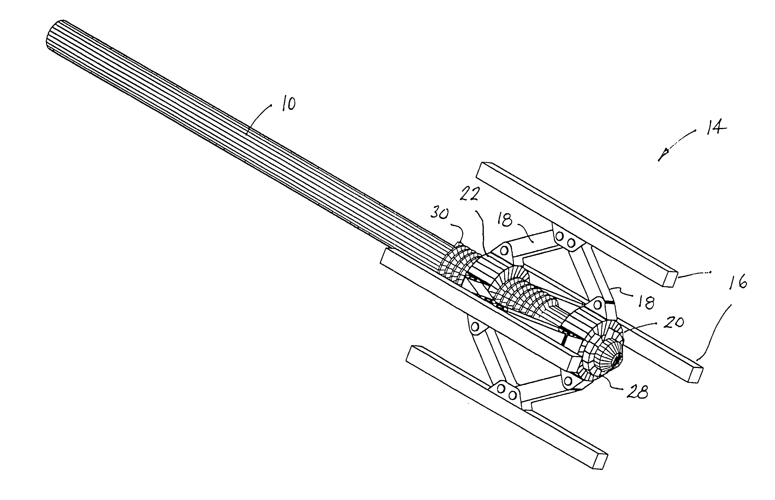
Image

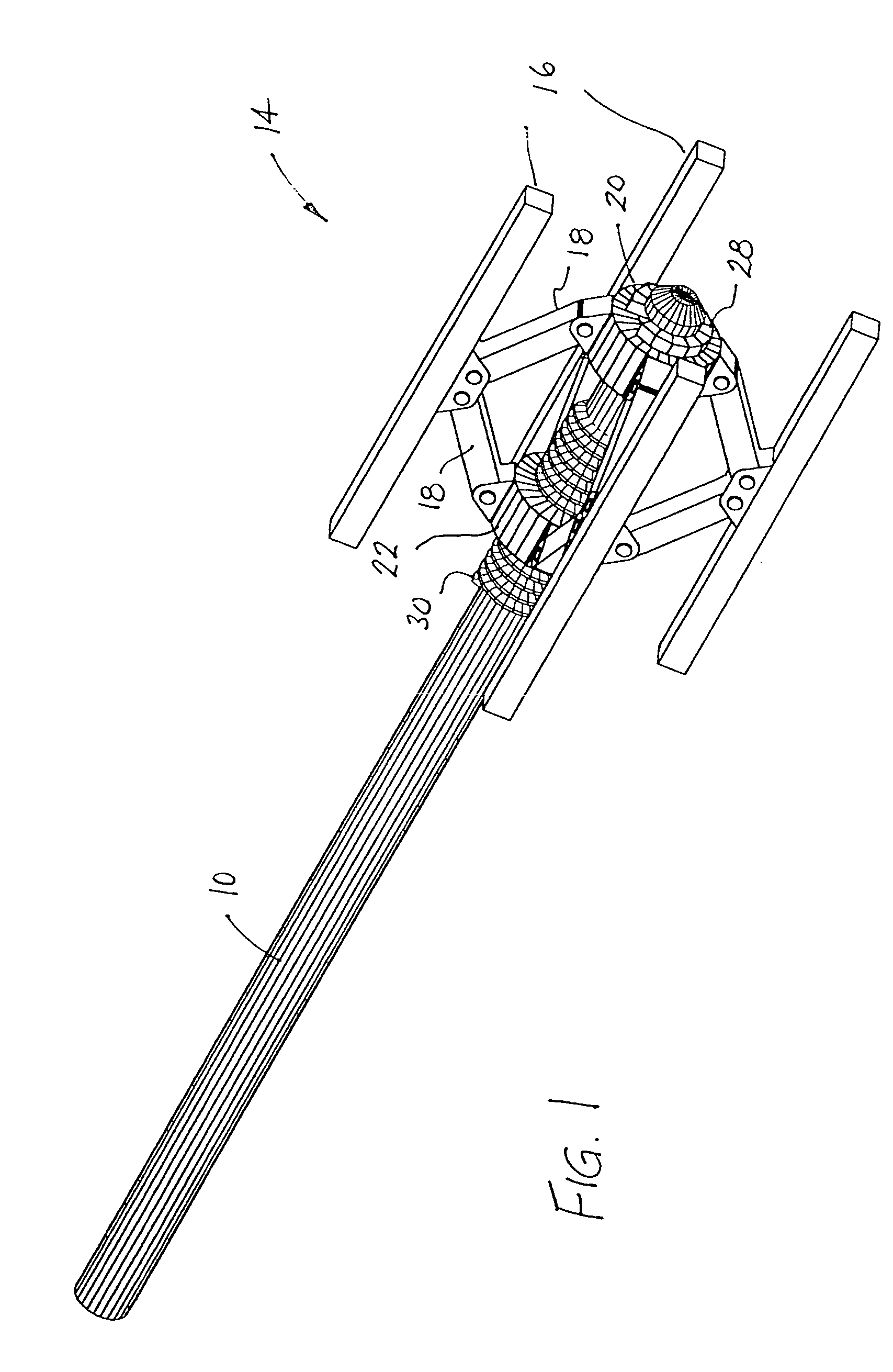
  • Mechanical bone tamping device for repair of osteoporotic bone fractures
  • Mechanical bone tamping device for repair of osteoporotic bone fractures
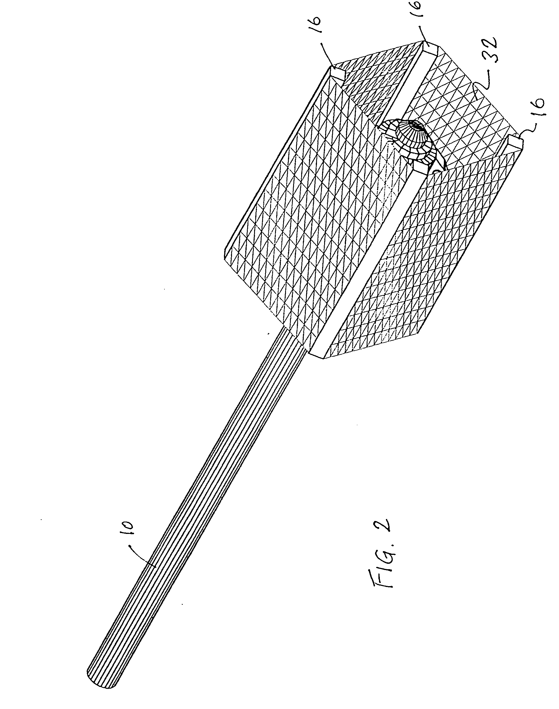
  • Mechanical bone tamping device for repair of osteoporotic bone fractures

Examples


Embodiment Construction

)

[0021] A screw jack tamp or lever arm bone compression mechanism designed to create a cavity within the bony contents of a vertebral body to allow or facilitate the stabilization of said vertebral body by instillation of bone cement or other stabilizing material (biological or inert) to repair, splint or otherwise stabilize bone structures weakened by benign or malignant processes (osteoporosis or malignant infiltration).

[0022] The screw jack tamp or lever arm bone compression instrument includes a shaft having a handle at one end to allow mechanical rotation of the shaft and a radially expandable structure at the other end having two, three, four or more hinged arms connected at their midpoint by a pivot and at their ends by a pair of collars separated along the length of a screw thread of the shaft. The arrangement being such that rotation of the shaft causes changes in the spacing between the collars along the threaded portion of the shaft such that the collars are approximated...


PUM


Abstract

A mechanical bone tamping device for osteoporotic repair include a pair of arms mounted on a spreading mechanism such as a screw jack. The mechanism is introduced into a small hole in a vertebra through a cannula, and is then operated to spread the arms apart, forming a cavity which may be filled with cement to fortify the vertebra.

Description

[0001] This application is a continuation of Ser. No. 10 / 230,256, filed Aug. 29, 2002.BACKGROUND OF THE INVENTION [0002] Pathologic fracture of the spinal vertebral body is very common. Bones weakened by osteoporosis or by malignant processes account for a large proportion of vertebral fractures. Most such fractures occur as a result of trivial trauma and are due to the weakened architecture of the bone through loss of bone calcium and associated alteration of bony trabecular support or through frank replacement of bony tissue by malignant cells. [0003] The injection of bone cement into the vertebral body to strengthen or stabilize it is a well recognized process that provides immediate stability to the weakened or compressed vertebral body that has been altered by disease. Present systems designed to inject bone cement into the vertebra weakened by disease (malignant or benign) generally utilize two types of processes. The first process involves simply injecting liquid bone cement ...

Claims


Application Information

Patent Timeline
IPC IPC(8): A61BA61B17/00A61B17/60A61B17/70A61B17/88A61F2/00A61F5/04A61M29/00
CPCA61B17/8858A61F2/4601A61F2002/30471A61F2002/30556A61F2002/4627
Inventor SUDDABY, LOUBERT
Owner SUDDABY LOUBERT
Learn More