Leaves and yard debris removal tool

Inactive Publication Date: 2005-06-09
HIERATH LEONARD L
View PDF32 Cites 2 Cited by
  • Summary
  • Abstract
  • Description
  • Claims
  • Application Information

AI Technical Summary

Benefits of technology

[0009] Against this backdrop the present invention has been developed. The present invention is directed to an apparatus for the removal of leaves or other debris which utilizes a blade design which seeks to optimize strength and capacity without incurring increased weight. This is achieved through the use of a continuously curved blade design having a concave upper edge and a straight lower edge. The upper, curved, portion of the blade maximizes the volume, while the straight lower edge optimizes the ability to grasp small, fine debris. The continuous curved shape provides a strong, self supporting blade which needs minimal bracing.
[0013] Further in accordance with the invention, the side edges of the blades are formed in a straight line from a point near where the upper edges are interconnected to the outer corners of the lower edges. In this way, the sides of the blades, as well as the lower edges, meet when the blades are closed. This helps retain even fine debris within the cavity of the blades.
[0014] Still further in accordance with the invention, the lower edge is preferably as wide, or wider than the body of the tool, this improves the ability of the tool to sweep a surface clean of debris and then grasp that debris across the full width of the tool.
[0015] The advantages of such an apparatus are a lightweight, strong debris removal tool that can be manufactured from a minimal number of parts and at a low cost. The blade design is self supporting, capable of resisting both grasping and tamping forces encountered in use, and which lends itself to both injection molding and thermal forming from sheet materials.

Problems solved by technology

Many designs exist, but the tool has yet to be perfected.
Part of the reason for this is that the conflicting requirements placed on such a tool push the designer to compromise.
This patent also illustrates one of the drawbacks to this approach: the lower edges of the blades do not naturally meet.
This greatly reduces the tool's effectiveness, especially with fine, loose debris.
Altering the shape of the blades to make the edges meet typically results in reduced capacity or edges which curve inward, causing them to trap debris rather than releasing it cleanly.
The region at which the edges meet is often substantially smaller that the width of the blades, reducing their 23 effectiveness.
The use of a cylinder offers good capacity, but strength and rigidity is compromised.
This is often done by the user pressing on the debris with a foot or hand, because the tool is unsuitable for this purpose.
A tool which is optimized for grasping often lacks the structural strength to then tamp that same debris.
The most common problem encountered is that the blades flex and may even break.
Many other designs have been used, but one or more of the desired criteria is always compromised.

Method used


Image

  • Leaves and yard debris removal tool
  • Leaves and yard debris removal tool
  • Leaves and yard debris removal tool

Examples


embodiments

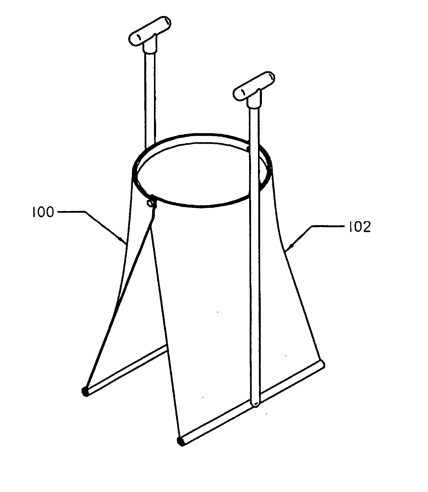
[0036] One embodiment of a debris removal tool according the to present invention is illustrated in FIGS. 1-3. As shown, it comprises two opposing substantially identical halves, 100&102, pivotally connected by pins or bolts, 101, so that they can open and close. The novelty of the invention is primarily in the configuration and construction of the blade element of the scoop. Its shape allows it to form the majority of the structure of the tool with the addition of only a few parts necessary to complete the tool. The upper corners of the opposing blades are pivotally connected so that as the handles are moved outward, the lower edges of the blades move together.

[0037] Each half of the tool preferably comprises the same identical set of elements. For simplicity the structure of only one half will be described, with the understanding that the discussion applies equally to the other half.

[0038] Referring to FIG. 4 the elements of a first embodiment of the tool can be seen. Central to...


PUM


Abstract

A debris removal tool having a pair of opposing pivoting blades each having a shape providing light weight and inexpensive manufacture. The blade is a continuous, smooth curve from a straight lower edge to an arcuate, generally semi-circular, upper edge. The outer corners of the upper edges of opposing, complementary blades are pivotally connected to define a pivot axis therebetween. When the blades close, their straight sides and straight lower edge mate, to form a closed bottom, somewhat upright cone shape with a straight bottom edge fully enclosing the debris. The lower edge of each blade is parallel to the pivot axis and may include serrations to enhance grasping of debris. Reinforcing gussets and handle retaining bosses may be provided in the blade to retain the handles and maintain tool rigidity while remaining light in weight.

Description

CROSS REFERENCE TO RELATED APPLICATIONS [0001] This application is a continuation-in-part of U.S. patent application Ser. No. 10 / 339,089 filed Jan. 9, 2003, entitled Leaves and Yard Debris Removal Tool, and claims the benefit of priority of U.S. provisional application Ser. No. 60 / 534,907, filed Jan. 8, 2004, the disclosures of which are hereby incorporated by reference in their entirety.FIELD OF THE INVENTION [0002] The present invention relates to the field of tools for grasping and moving loose material and specifically to such tools intended for moving leaves or other lawn and garden debris. BACKGROUND OF THE INVENTION [0003] Tools for gathering and removing leaves and other loose debris are well known in the art. Many designs exist, but the tool has yet to be perfected. Part of the reason for this is that the conflicting requirements placed on such a tool push the designer to compromise. The ideal tool would have large capacity, high strength, and light weight; be efficient in ...

Claims


Application Information

Patent Timeline
IPC IPC(8): A01D11/00
CPCA01D11/00
Inventor HIERATH, LEONARD L.
Owner HIERATH LEONARD L
Why Eureka
Try Eureka