
Image forming method and apparatus for fixing an image

a technology of fixing member and fixing surface, which is applied in the field of method and apparatus for fixing image, can solve the problems of deteriorating image quality, surface of fixing member contacting recording medium (such as paper) not meeting microscopic concavities and convexities of recording medium, and orange peel surface problem, etc., and achieves the effect of effective fixing imag

Active Publication Date: 2005-06-02
RICOH KK
View PDF58 Cites 29 Cited by
  • Summary
  • Abstract
  • Description
  • Claims
  • Application Information

AI Technical Summary

Benefits of technology

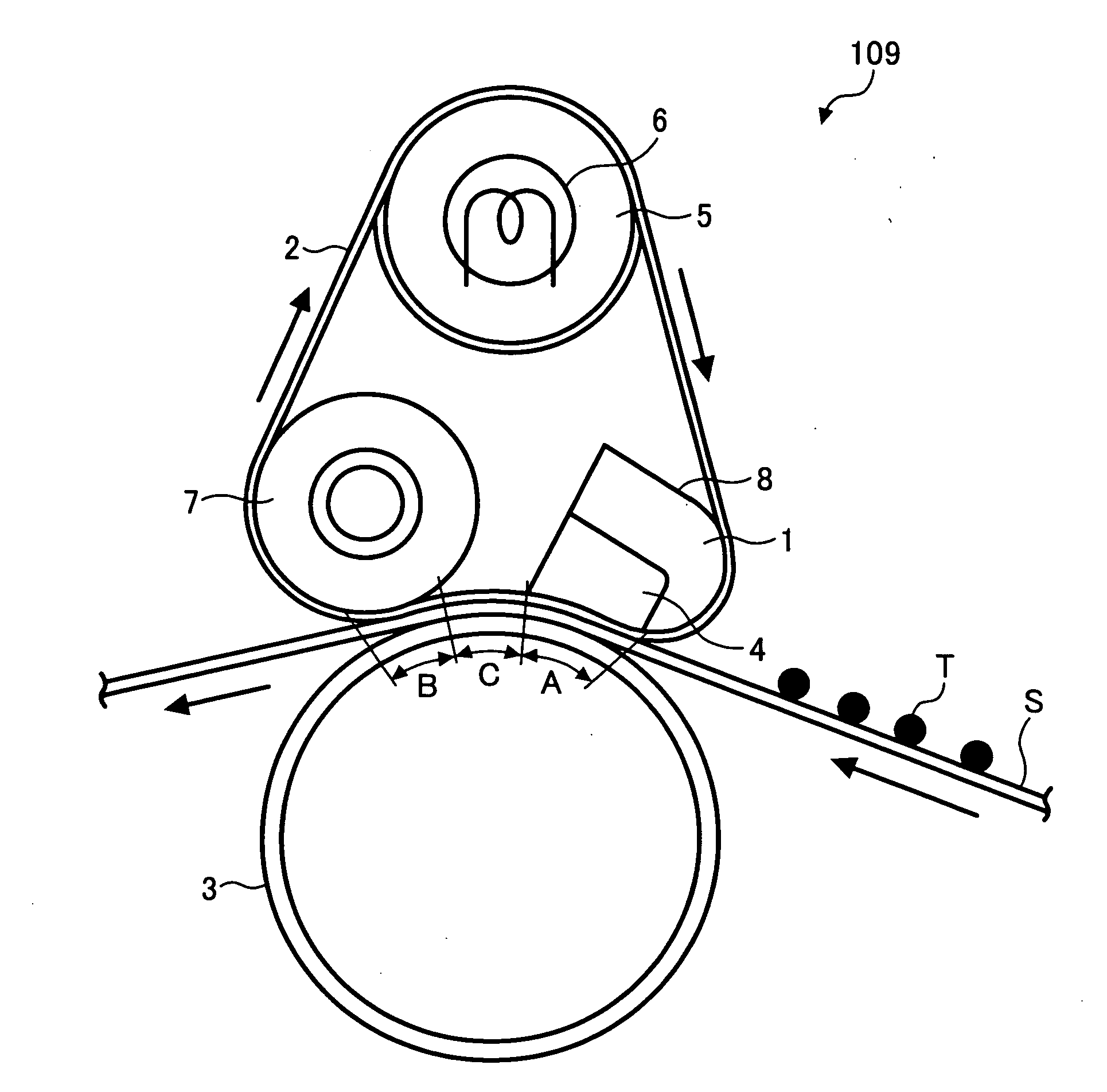
[0017] The present invention can still further provide a method for image forming for effectively fixing an image, including providing a first endless moving member configured to rotate, providing a second endless moving member configured to rotate to form a nip area together with the first endless moving member, rotating the first and second endless moving members, forming a toner image on a recording medium, conveying the recording medium to the nip area, and fixing, at the nip area, the toner image disposed on the recording medium onto the recording medium with heat and pressure, wherein the second endless moving member includes a surface layer having a universal hardness HU and a maximum nip surface pressure P each within a predetermined range.
[0019] The present invention can still further provide a method for effectively fixing an image, including providing a first endless moving member configured to rotate, providing a second endless moving member configured to rotate to form a nip area together with the first endless moving member, rotating the first and second endless moving members, forming a toner image on a recording medium, conveying the recording medium to the nip area, and fixing, at the nip area, the toner image disposed on the recording medium onto the recording medium with heat and pressure, wherein the second endless moving member includes a surface layer having a universal hardness HU and a maximum nip surface pressure P each within a predetermined range.

Problems solved by technology

If the fixing member is formed of a rigid material and does not have a surface layer formed by the elastic layer, a surface of the fixing member contacting the recording medium (such as paper) does not fit microscopic concavities and convexities of a surface of the recording medium.
As a result, the surface of the fixing member fails to closely contact the surface of the recording medium, resulting in deterioration in image quality (such as microscopic uneven glossiness of the image).
This problem is notably observed in an image formed by the color image forming apparatus, while the problem may not be particularly noticeable in an image formed by a monochrome image forming apparatus.
In the fixing method in which low pressure is applied to a nip, however, the orange peel surface problem occurs.
Further, the nip needs to have a large nipping area required for performing the image fixation.
This attempt using the residual heat, however, is not preferable from a viewpoint of energy reduction.
However, due to the configuration in which the heat source is provided at the nip, it is difficult to apply sufficient surface pressure for preventing influence of the microscopic concavities and convexities of the recording medium surface.
If a thick rubber layer is used to form the flexible surface layer, however, the amount of the heat required for heating the fixing member increases.
As a result, the start-up time increases, making it difficult to perform the on-demand fixing method.
As described above, it is difficult to provide a fixing device capable of both reducing the start-up time and energy consumption and performing high-quality image fixation not affected by the microscopic concavities and convexities of the surface of the recording medium.

Method used


Image

  • Image forming method and apparatus for fixing an image
  • Image forming method and apparatus for fixing an image
  • Image forming method and apparatus for fixing an image

Examples


Embodiment Construction

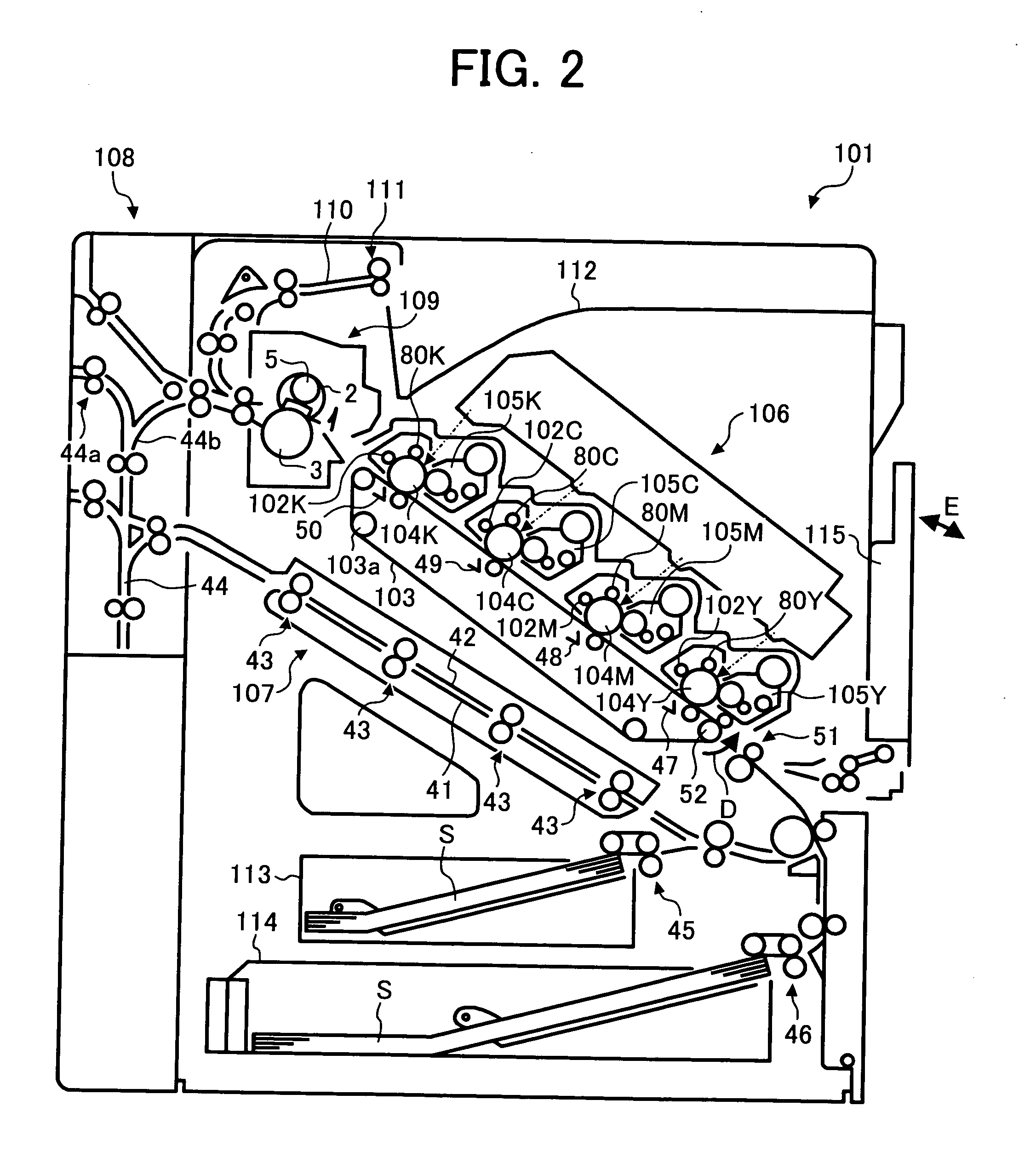
[0030] In describing preferred embodiments illustrated in the drawings, specific terminology is employed for the purpose of clarity. However, the disclosure of this patent specification is not intended to be limited to the specific terminology used, and it is to be understood that substations for each specific element can include any technical equivalents that operate in a similar manner. Referring now to the drawings, wherein like reference numerals designate identical or corresponding parts throughout the several views, FIG. 2 illustrates a configuration of a full-color printer using an electrophotographic method, as an example of the image forming apparatus according to the embodiment of the present invention.

[0031] As shown in FIG. 2, the full color printer 101 includes: photoconductor units 102Y, 102M, 102C, and 102K; a transfer belt 103; photoconductors 104Y, 104M, 104C, and 104K; developing devices 105Y, 105M, 105C, and 105K; a writing device 106; a duplex unit 107; a revers...


PUM


Abstract

An image forming apparatus, includes an image forming mechanism configured to form an image, and a fixing unit configured to fix a toner image formed on a recording medium. The fixing unit includes a fixing device having a first endless moving member configured to rotate, and a second endless moving member configured to rotate to form a nip area together with the first endless moving member to fix, at the nip area, a toner image disposed on the recording medium onto the recording medium with heat and pressure, the second endless moving member including a surface layer having a universal hardness HU and a maximum nip surface pressure P each within a predetermined range.

Description

CROSS REFERENCE TO RELATED APPLICATION [0001] This application claims priority to Japanese patent application No. 2003-400499, filed on Nov. 28, 2003, the disclosure of which is incorporated by reference herein in its entirety. BACKGROUND OF THE INVENTION [0002] 1. Field of the Invention [0003] The present invention relates to a method and apparatus for image forming, and more particularly to a method and apparatus for image forming capable of effectively fixing a visible image on a recording medium. [0004] 2. Discussion of the Related Art [0005] In a typical conventional image forming apparatus, a latent image formed on an image carrying member is developed with toner supplied from a developing device, and a visible toner image is formed on the image carrying member. The toner image formed on the image carrying member is then transferred to a recording medium by a transferring device and is fixed on the recording medium by a fixing device. Fixing members used in the fixing device i...

Claims


Application Information

Patent Timeline
Patent Type & Authority Applications(United States)
IPC IPC(8): G03G15/20
CPCG03G15/2064
Inventor NAKAFUJI, ATSUSHIKUNII, HIROYUKISOMEYA, YUKIMICHIECHIGO, KATSUHIROFUJITA, TAKASHIKIKUCHI, HISASHIBABA, TOSHIHIKOKUROTAKA, SHIGEO
Owner RICOH KK
Learn More