
VRRP technology keeping VR confidentiality

a packet transmission router and confidentiality technology, applied in the field of packet transmission routers, can solve problems such as the leakage of information about the routing table that each vr manages

Inactive Publication Date: 2005-06-02
HITACHI LTD
View PDF7 Cites 39 Cited by
  • Summary
  • Abstract
  • Description
  • Claims
  • Application Information

AI Technical Summary

Benefits of technology

The invention is a packet transmission router that can maintain the connection to user terminals even if any trouble occurs. It uses a virtual router called VR to manage the routing table for each user. The invention also includes a means to distinguish the data of the routing table that each VR manages when it is transferred to the standby router. This prevents information leakage and ensures that the standby router can take over the process without losing the information about the route that the active router has managed. The technical effect of the invention is to maintain the reliability and security of the network connection even in the event of a failure of the active router.

Problems solved by technology

However, if VRRP is simply applied to the virtual router VR, it will be supposed that information about the routing table that each VR manages could leak out.

Method used


Image

  • VRRP technology keeping VR confidentiality
  • VRRP technology keeping VR confidentiality
  • VRRP technology keeping VR confidentiality

Examples


embodiment 1

[0033]FIG. 6 shows the situation in which an embodiment of the invention, or a redundancy packet transmission router with a VR function incorporated is actually provided on the network. The redundancy packet transmission router of this embodiment includes the active packet transmission router 11 and the standby packet transmission router 12 each of which has virtual routers VR 1, VR 2 activated. When the virtual routers of the standby router 12 are not operated, the active router 11 sends a VR boot order as a trigger to the standby router 12, causing its virtual routers VR to operate. The active router 11 has a plurality of communication ports of which certain ones are assigned to interfaces 31, 33 for ISP 1 and of which the other ones are assigned to interfaces 32, 34 for ISP 2. InFIG. 6, VR 1 manages the transmission and reception of packets to ISP 1, and VR 2 does the transmission and reception of packets to ISP 2. Similarly, the standby router 12 has a plurality of communication...

embodiment 2

[0051] In some case, a session is provided between the active router and a node. The term session stands for one-to-one connection generated between a router and a node by a protocol such as PPP (Point to Point Protocol). In the case of a session communication, each session incidentally generates a data transmission parameter acquired by the negotiation between the active router and a node. The parameters generated are, for example, transaction information such as password and amount of money that the user enters in e-commerce or a data group that describes the association between the identifiers (session identifiers) that the router uniquely assigns to each node in order to manage it and the identifiers (node ID) peculiar to nodes that are determined by an external organization. In this embodiment, this information is called session information.

[0052] Referring to FIG. 6, when a session is set up between the node 1 and the VR 1 of the router 11, negotiation for a plurality of para...


PUM


Abstract

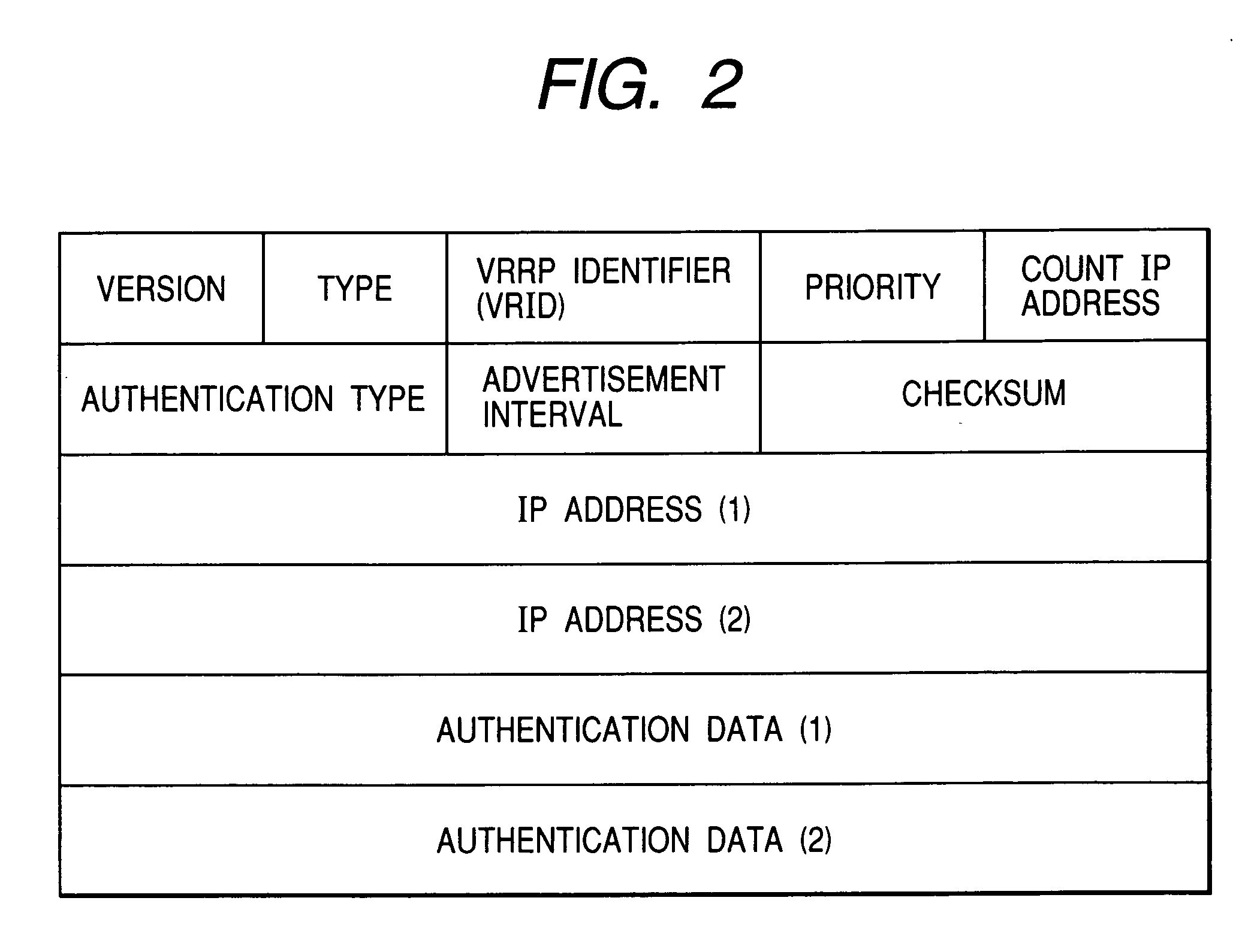
In a packet transmission router used in a VRRP (Virtual Router Redundancy Protocol) network having a VR (Virtual Router) function, when virtual routers VR are realized by the VRRP, the routing control information that each VR manages is prevented from being mixed with that of other VR. When an active packet transmission router transmits a VRRP packet to a standby packet transmission router, an identifier indicating which virtual router belongs to the VRRP packet is added to the VRRP packet before the transmission of the VRRP packet.

Description

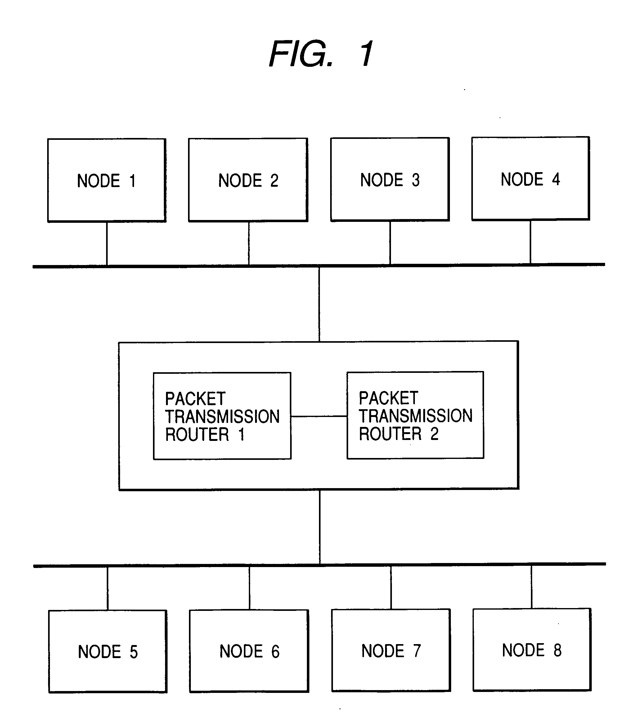
BACKGROUND OF THE INVENTION [0001] The present invention relates to a packet transmission router to be used for a VRRP (Virtual Router Redundancy Protocol) network having a VR (Virtual Router) function. [0002] The VRRP is the technology for improving the reliability of the packet transmission router used in the network. In the VRRP, a packet transmission router is physically composed of a plurality of packet transmission routers for redundancy so that even if a single one of those routers fails, the other ones can take over the process from the damaged router to keep the operation of the whole packet transmission router not stopped. The router that is now processing packets is called the active packet transmission router, and the spare router that operates when the active router fails is called the standby packet transmission router. [0003]FIG. 1 shows an example of the packet transmission router having the VRRP function incorporated. As illustrated in FIG. 1, the nodes 1˜8 provided...

Claims


Application Information

Patent Timeline
Patent Type & Authority Applications(United States)
IPC IPC(8): H04L12/28H04L12/46H04L45/586
CPCH04L45/586H04L45/00H04L45/76
Inventor IIJIMA, TOMOYUKITAKIHIRO, MASATOSHIHINO, MASAYUKI
Owner HITACHI LTD
Learn More