
Expandable reamer

a reamer and expandable technology, applied in the field of reamers, can solve the problems of lengthening the healing and rehabilitation time of patients after surgery, and achieve the effect of prolonging the healing time and rehabilitation tim

Inactive Publication Date: 2005-05-26
ZIMMER TECH INC
View PDF11 Cites 206 Cited by
  • Summary
  • Abstract
  • Description
  • Claims
  • Application Information

AI Technical Summary

Benefits of technology

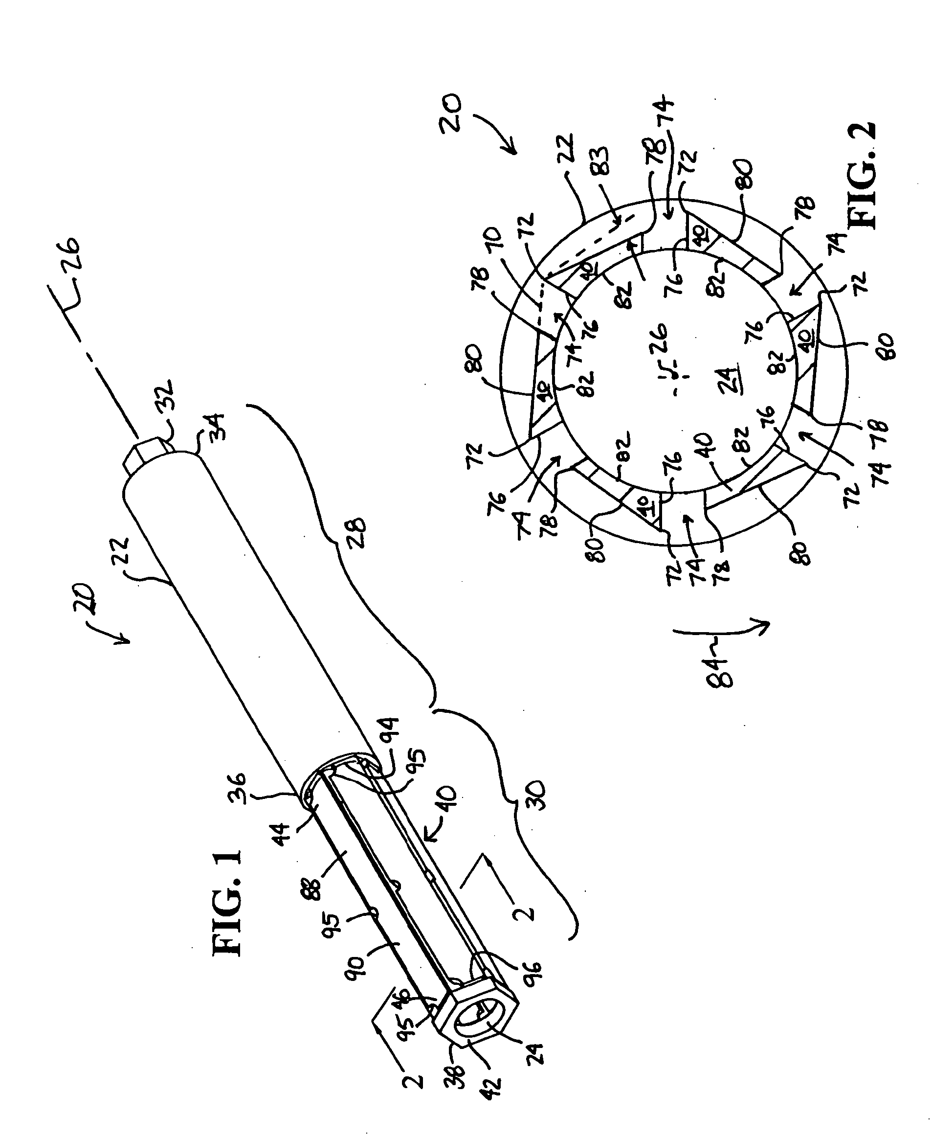
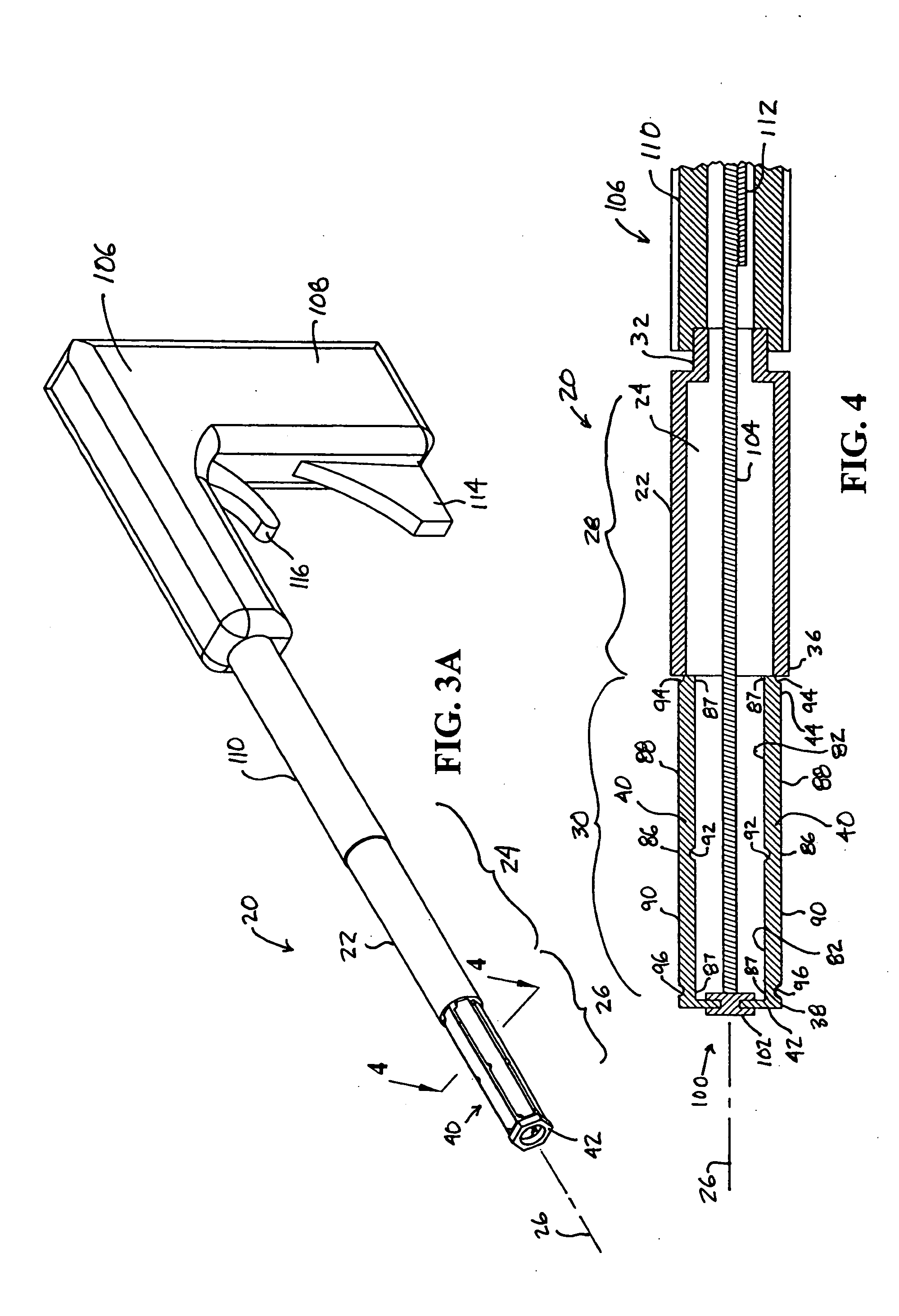
[0011] By proximally drawing the ring and distal end of the blades toward the proximate end of the blades, deformation of the blades at the deformation points allows the segments to extend radially outward from the longitudinal axis of the reamer, thereby increasing the diameter of the reamer body. Distally advancing the distal ring along the longitudinal axis away from the proximate end of the blades will cause the blades to contract radially inward toward the longitudinal axis, thereby returning the reamer body to its original diameter and the blades to a contracted position substantially parallel to the longitudinal axis of the reamer.
[0012] In one exemplary embodiment, the deformation points at which the blades are coupled to the distal ring and to the shank and which separate adjacent blade segments may be defined simply by exterior or interior circumferential reliefs or grooves which reduce the material thickness and therefore reduce resistance of the blades to bending at the various desired points. The deformation points may also be further defined by radially oriented arcuate cuts which intersect the circumferential reliefs.
[0013] In one exemplary embodiment of the invention, the blades are easily and inexpensively formed from a reamer body having a polygonal cross-section, such as a hexagon. The slots may be milled parallel to and coincident with the apex formed between adjacent sides of the polygon. By locating the slots in this way, each apex and the milled face which extends radially inward form cutting edges, and the opposite milled face of the slot forms the trailing edge, or flute, of an adjacent blade. Formed in this fashion, the cutting edge, being the former apex of the polygon, has a greater radius than the trailing edge. Thus, only the cutting edge contacts the surface being reamed.
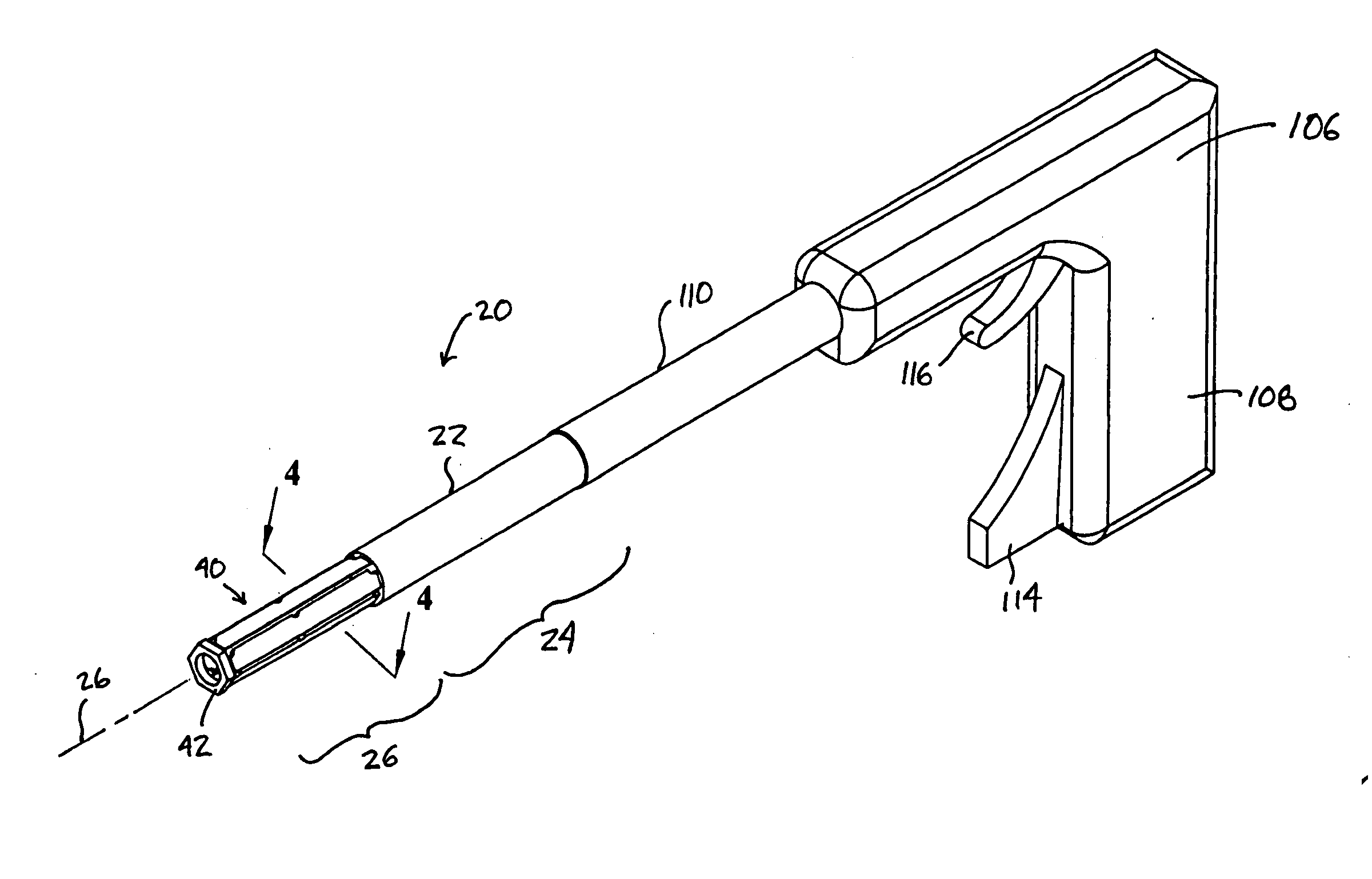
[0015] In order to ream a cavity in a bone that is larger than the incision in the soft tissue and the entry aperture into the bone, the expandable reamer is first inserted through the incision and the aperture in the bone. Then, the reamer is expanded during rotation by drawing a distal end of the reamer body toward the proximate end of the reamer body. Upon achieving the desired expansion diameter and thereby cavity size, the distal end of the expandable reamer may be advanced away from the proximate end of the reamer body, thereby collapsing the diameter of the expandable reamer so that it may be removed from the cavity and withdrawn through the entry aperture and incision.
[0021] Advantageously, the present invention provides a low-cost and potentially disposable reamer that provides a predefined reamer body shape which is expandable after insertion into the bone structure, which includes deformable blades that are secured at both a distal and a proximate end, and which may include a distal end cutter for boring the initial bore into the bone structure.

Problems solved by technology

While this approach provides surgeons with an excellent view of the bone surface and open access for various sized and shaped instruments such as cutting and reaming instruments, the underlying damage to the soft tissue, including the muscles, can lengthen a patient's healing and rehabilitation time after surgery.

Method used


Image

  • Expandable reamer
  • Expandable reamer
  • Expandable reamer

Examples


Embodiment Construction

[0032] The embodiments disclosed below are not intended to be exhaustive or limit the invention to the precise forms disclosed in the following detailed description. Rather, the embodiments are chosen and described so that others skilled in the art may utilize their teachings.

[0033] First exemplary expandable reamer 20, shown in FIG. 1, is formed from cannulated shaft 22 having bore 24 therethrough along longitudinal axis 26. Reamer 20 includes shank 28 and reamer body 30. Chuck end 32 for driving reamer 20 is located at proximate end 34 of shank 28. Reamer body 30 extending from distal end 36 of shank 28 to distal end 38 of reamer 20 includes deformable cutting blades 40 and ring 42. Blades 40 are coupled at proximate end 44 to distal end 36 of shank 28. Blades 40 are also coupled at distal end 46 to ring 42. Advantageously, as ring 42 is proximally drawn toward proximate end 32 of reamer 20, at least a portion of blades 40 extend radially outward from longitudinal axis 26, thereb...


PUM


Abstract

An expandable reamer includes, in one exemplary embodiment thereof, a cannulated shaft and a plurality of straight cutting blades having deformable points. The blades are hingably outwardly rotatable at the deformation points between a contracted position and an expanded position. In the contracted position, the blades are substantially parallel to the longitudinal axis of the cannulated shaft and, in the expanded position, the blades have at least a portion oriented radially outward from the longitudinal axis, thereby forming a larger diameter cutting surface in the expanded position and in the contracted position. The blades are formed from a portion of the cannulated shaft by, e.g. milling longitudinally extending slots through the wall of the cannulated shaft, the slots serving as flutes dividing the cutting edge and trailing edge of each adjacent blade. Each blade may also include more than one segment arranged along its length, the segments coupled by deformation points. The expandable reamer may be used for cutting a cavity in a bone or other structure that is larger than the diameter of the entry point into the bone and greater than the diameter of the contracted reamer.

Description

BACKGROUND [0001] The present invention relates to reamers and, more specifically, to reamers having expandable reaming heads. [0002] Reamers are typically used for enlarging the diameter of a bore which has been drilled or otherwise cut in a material. Reamers generally include a shank for driving the reamer and a reamer body that includes cutting edges. Hand or powered rotation of a reamer cuts or shaves the material surface defining the bore, removing material and increasing the diameter of the bore. [0003] Certain reaming applications require the reaming of a cavity that is larger in diameter than an aperture allowing access to the cavity. One known expandable reamer used for spinal surgical procedures provides an elongated shaft assembly having a pair of opposing blades rotatably mounted in a scissor-like fashion at the distal end of the shaft assembly. After insertion of the distal end of the shaft assembly through an aperature leading to a bore in a bone structure, the blades ...

Claims


Application Information

Patent Timeline
Patent Type & Authority Applications(United States)
IPC IPC(8): A61B17/16A61B17/56
CPCA61B17/1617A61B2017/1602A61B17/1668
Inventor LOZIER, ANTONY J.PACELLI, NICOLAS J.THELEN, SARAH L.
Owner ZIMMER TECH INC
Learn More