
Headspace insulator for electrochemical cells

a technology of electrochemical cells and headspace, applied in the field of power sources, can solve the problems of affecting the performance of electrochemical cells, unable to hold the feedthrough pin in a uniform isolated location, and prone to deformation

Active Publication Date: 2005-05-26
MEDTRONIC INC
View PDF2 Cites 28 Cited by
  • Summary
  • Abstract
  • Description
  • Claims
  • Application Information

AI Technical Summary

Benefits of technology

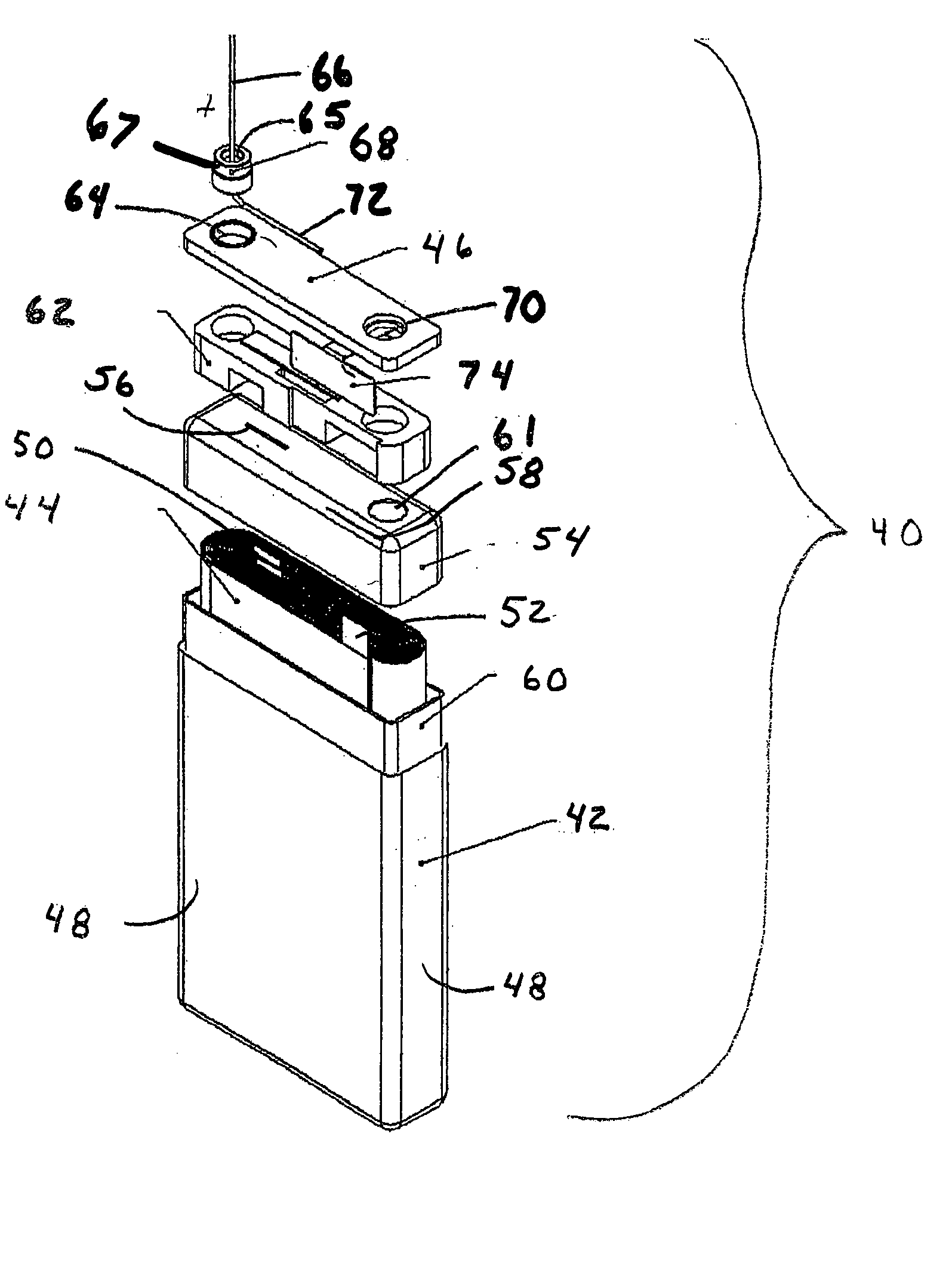
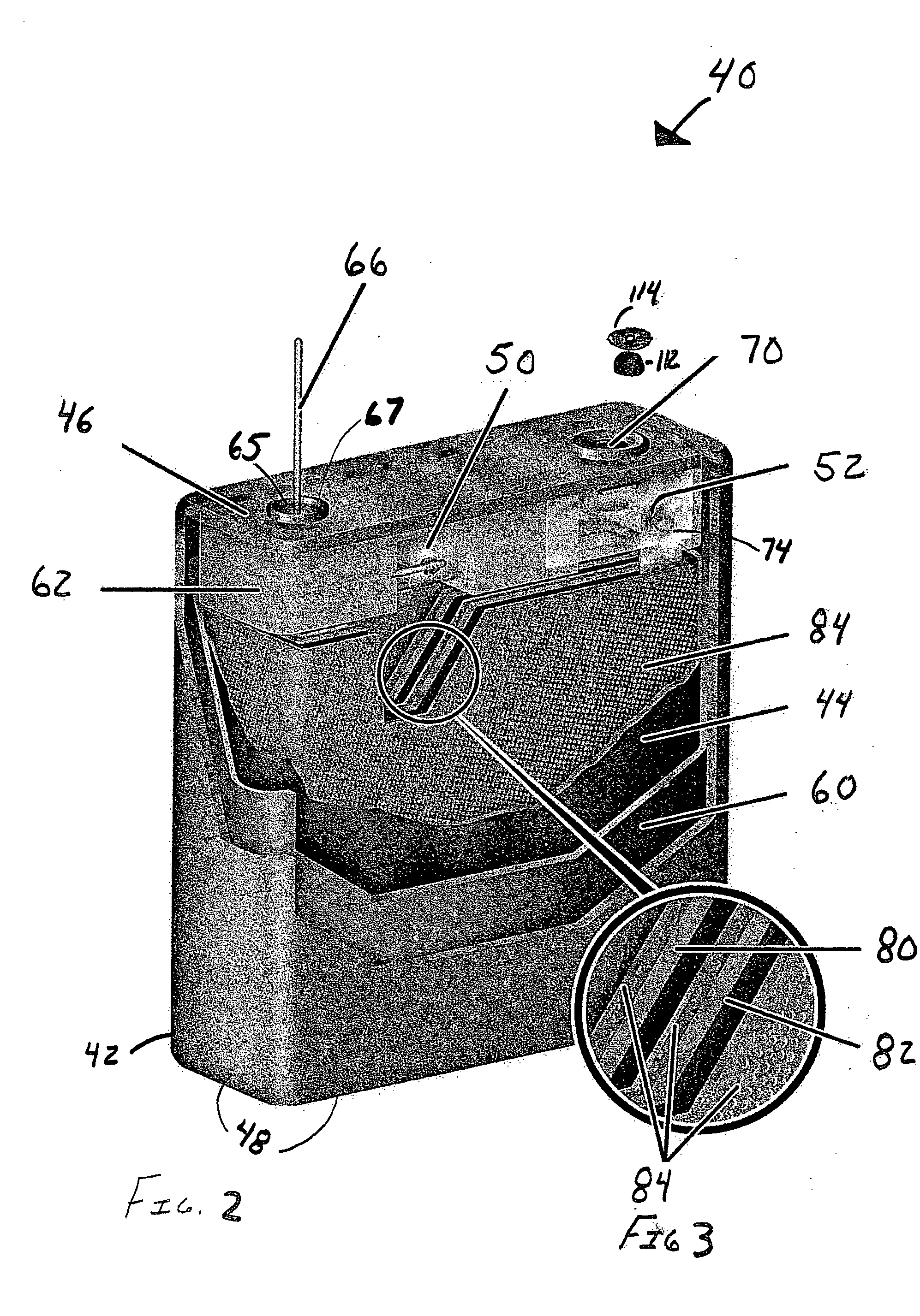
[0010] A battery in embodiments of the invention may include one or more of the following features: (a) an electrode assembly having a second electrode tab and a first electrode tab, (b) a battery case having the electrode assembly within the battery case, (c) a battery cover having a feedthrough, the battery cover being coupled to the battery case, (d) a headspace insulator having a receiving area, (e) a feedthrough assembly having a ferrule, feedthrough pin, and insulating member, the feedthrough pin having a distal end locked into the receiving area and coupled to the second electrode tab, (f) a weld bracket coupled to the battery cover, the weld bracket being coupled to the first electrode tab, (g) a second electrode opening to accept the second electrode tab, and a first electrode opening to accept the first electrode tab, (h) a case liner, (i) a coil insulator having slits, the coil insulator and the case liner enclosing the electrode assembly with the second electrode tab and the first electrode tab extending through the slits.
[0011] A headspace insulator for a battery in an IMD in one or more embodiments of the present invention may include one or more of the following features: (a) a body of electrically and thermally insulating material disposed between a battery electrode assembly and a battery cover, (b) a receiving area within the body that receives and isolates a battery feedthrough pin, (c) an indentation within the receiving area that holds the feedthrough pin in place once the feedthrough pin is within the receiving area, (d) a raised portion that couples to a ba...

Problems solved by technology

Specifically, these prior solutions cannot hold the feedthrough pin in a uniform isolated location.
However, with a bend in the feedthrough pin there is little give to prevent any fatigue of the wire or the joint where the feedthrough pin enters the feedthrough through the glass during a shock or vibration event.
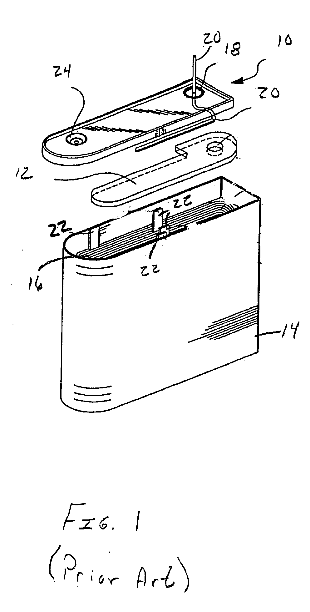
It is not precisely located with respect to other internal battery components and is susceptible to deformation during the assembly process.
While this condition does not present any compromise to the intent of the headspace insulator design, it can affect manufacturing yields.
This non-uniform pin length caused the case to cover insertion processing to be inconsistent.
However, this increased the length of the feedthrough pin, which in turn increased the resistance of the pin.
This was an undesirable result as the resistance consumed power from the battery.

Method used


Image

  • Headspace insulator for electrochemical cells
  • Headspace insulator for electrochemical cells
  • Headspace insulator for electrochemical cells

Examples


Embodiment Construction

[0021] The following discussion is presented to enable a person skilled in the art to make and use the invention. Various modifications to the illustrated embodiments will be readily apparent to those skilled in the art, and the generic principles herein may be applied to other embodiments and applications without departing from the spirit and scope of the present invention as defined by the appended claims. Thus, the present invention is not intended to be limited to the embodiments shown, but is to be accorded the widest scope consistent with the principles and features disclosed herein. The following detailed description is to be read with reference to the figures, in which like elements in different figures have like reference numerals. The figures, which are not necessarily to scale, depict selected embodiments and are not intended to limit the scope of the invention. Skilled artisans will recognize the examples provided herein have many useful alternatives fall within the scop...


PUM

PropertyMeasurementUnit
Areaaaaaaaaaaa

Abstract

A headspace insulator for a battery cell operatively coupled to circuitry within an implantable medical device in including one or more of the following: (a) a body of electrically and thermally insulating material disposed between a battery electrode assembly and a battery cover, (b) a receiving area within the body that receives and isolates a battery feedthrough pin, (c) an indentation within the receiving area retaining the feedthrough pin within the receiving area, (d) a raised portion coupled to a battery cover providing an air gap between the cover and the headspace insulator near case-to-cover weld areas, (e) a feedthrough aperture adapted to receive a feedthrough assembly, (f) a pin aperture that receives the feedthrough pin, (g) a fillport aperture for electrolyte fluid flow through the headspace insulator, and (h) a slot that locates a battery weld bracket and isolates it from the feedthrough pin.

Description

FIELD OF THE INVENTION [0001] The present invention relates to the field of power sources such as primary batteries, capacitors and rechargeable batteries for devices such as an implantable medical device (IMD). More particularly, the present invention relates to an improved headspace insulator for an electrochemical cell adapted to be operatively coupled to electronic circuitry within an IMD. Furthermore, the present invention relates to electrochemical cells comprising a novel headspace insulator and a method of fabricating an electrochemical cell incorporating said headspace insulator. BACKGROUND OF THE INVENTION [0002] Implantable medical devices are used to treat patients suffering from a variety of conditions. An example of an IMD include implantable pulse generators (e.g., a cardiac pacemaker) and implantable cardioverter-defibrillators (ICDs), which are electronic medical devices that monitor the electrical activity of the heart and provide electrical stimulation to one or m...

Claims


Application Information

Patent Timeline
IPC IPC(8): H01M6/16H01M10/04H01M50/176H01M50/528H01M50/636
CPCH01M2/06H01M2/22H01M2/361Y10T29/49108H01M6/16Y10T29/4911Y10T29/49114H01M2/365H01M50/528H01M50/636Y02P70/50H01M50/176
Inventor HOWARD, WILLIAM G.HAAS, DAVID P.LUND, JEFFREY S.
Owner MEDTRONIC INC
Learn More