
Driver device for recording head

a technology of driving device and recording head, which is applied in the direction of printing, other printing apparatus, etc., can solve the problems of increasing the number, lowering the reliability, and complex structur

Inactive Publication Date: 2005-05-26
BROTHER KOGYO KK
View PDF3 Cites 10 Cited by
  • Summary
  • Abstract
  • Description
  • Claims
  • Application Information

AI Technical Summary

Benefits of technology

[0017] The present invention has been developed in view of the above-described situations, and an object of the invention is, therefore, to provide a driver device fbr a recording head, which requires a reduced number of signal lines connecting the driver device to the circuit board in the main body, and where the increase in the required cost and the degree of structural complexity is minimized.
[0019] According to the arrangement where the print data signal comprises the selecting signal used for selecting one of the waveform signals and the non-selecting signal serving for another purpose, the number of data signal lines required can be reduced, compared to an arrangement where a selecting signal for selecting one of waveform signals and the non-selecting signal serving for another purpose are separately transmitted through respective signal lines.
[0025] Where the at least one combination not used for the wave form signal selection consists of a plurality of them, that is, where a plurality of combinations are left unused, a part or all of the unused combinations can be respectively used for a plurality of purposes different than the waveform signal selection. The plurality of purposes may include at least one of the above-indicated purposes (i) and (ii), or may not include any of them. In such a case where there are a plurality of combinations which are not used for the selection of one of the waveform signals but used for other purposes, respectively, the number of signal lines which can be omitted increases advantageously.

Problems solved by technology

Accordingly, the conventional arrangement is vulnerable to disconnection of lines when a physical force is applied onto the cable, lowering the reliability.
Further, with the increase in the number of nozzles, the pitch of leads of a connector connected to the driver IC, for instance, becomes small, making the structure complex.
In addition, increase in the number of core wires of the flexible printed circuit board (FPC) or flexible flat cable (FFC) pushes up the required cost.

Method used


Image

  • Driver device for recording head
  • Driver device for recording head
  • Driver device for recording head

Examples


first embodiment

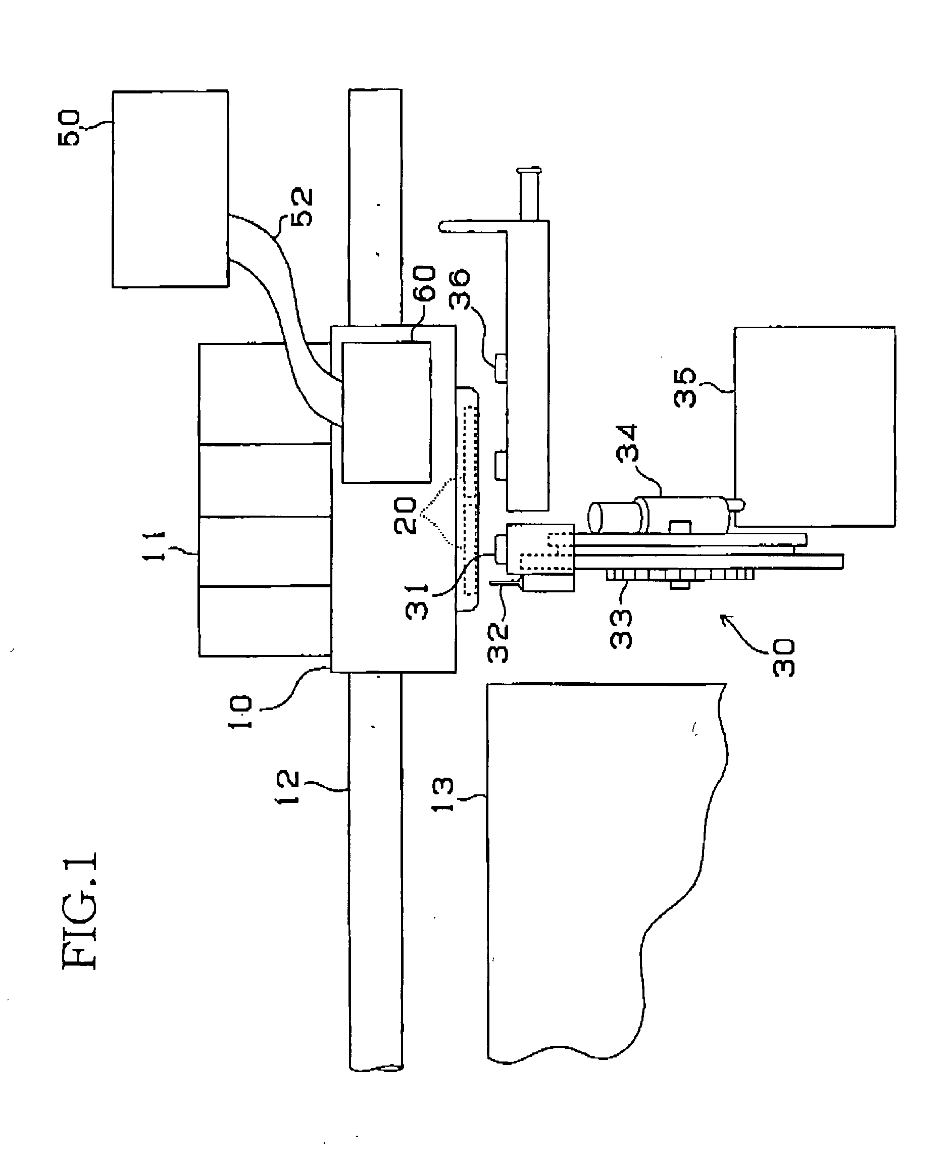
[0045] Referring to FIGS. 1-3, there will be described an ink jet printer according to a first embodiment of the invention.

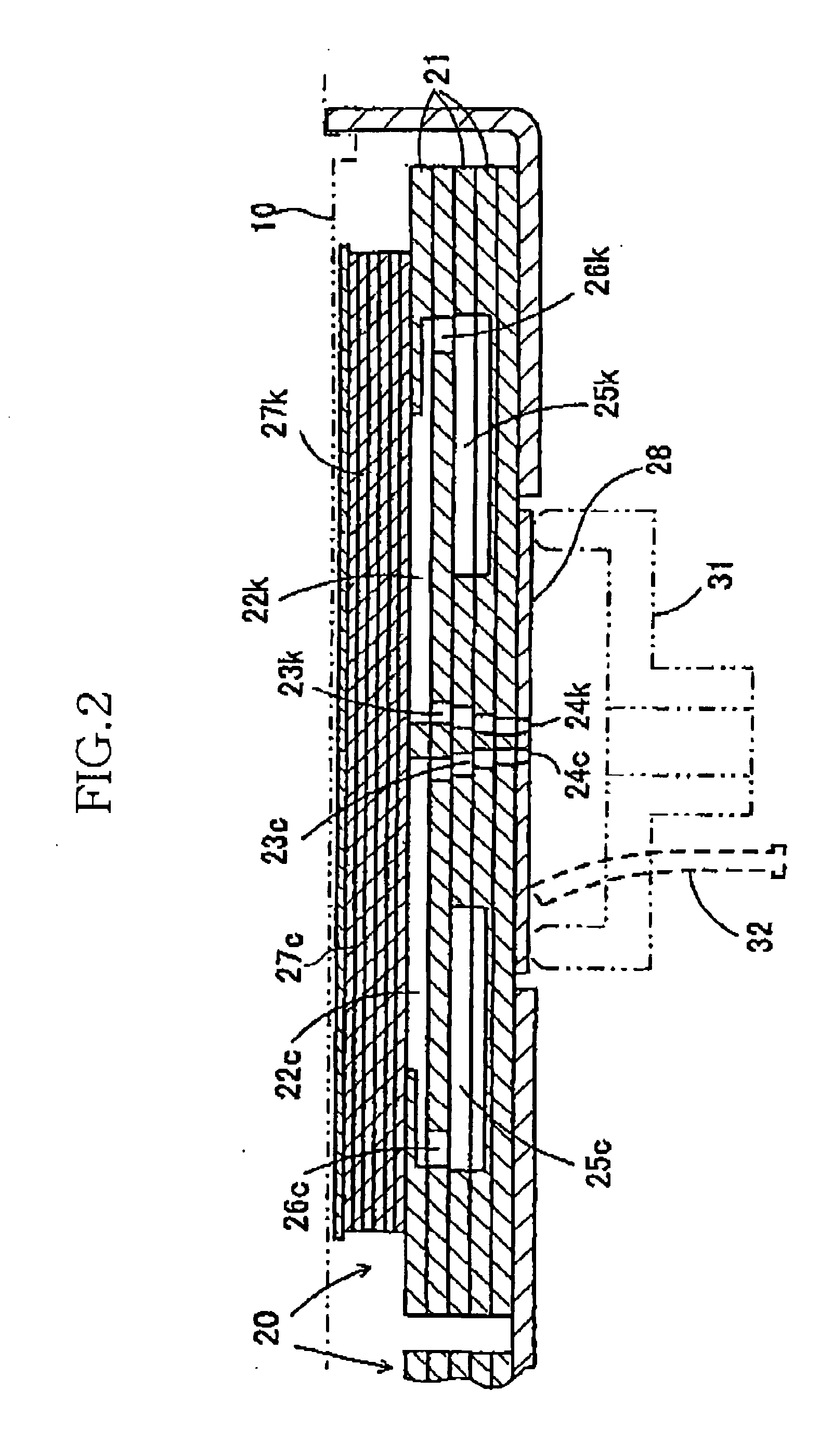
[0046] Two ink jet heads 20 are mounted on a carriage 10, as shown in FIG. 1, to be moved along a shaft 12 in parallel to a surface of a printing medium (printing paper) on a printing paper conveying portion 13, to eject droplets of ink onto the printing paper. On the carriage 10 are mounted four ink cartridges 11 incorporating inks of black, yellow, magenta, and cyan, respectively. The black ink and cyan ink are supplied to one of the two ink jet heads 20, while the yellow ink and magenta ink are supplied to the other ink jet head 20. As shown in FIG. 2, in a lower surface 28 (i.e., a nozzle surface) of the former ink jet head 20, a plurality of nozzles 24k for ejecting the black ink therethrough are formed in a row, and a plurality of nozzles 24c for ejecting the cyan ink therethrough are also formed in a row, the respective rows extending in the direction pe...

second embodiment

[0079] There will be described an ink jet printer according to a second embodiment of the invention. A structure of the ink jet printer of the second embodiment is identical with that of the first embodiment as described above with reference to FIGS. 1-3, except the circuit configuration of the driver IC 60. Therefore, description of the identical part of the second embodiment is omitted, by reference to FIGS. 1-3.

[0080]FIG. 9 shows a circuit configuration of the driver IC 60 of the ink jet printer according to the second embodiment, while FIG. 10 is a timing chart illustrating signals treated in the driver IC.

[0081] The structures of a D flip-flip 64, multiplexer 66, and drive buffer 68 are identical with that of the corresponding elements in the first embodiment described above by referring to FIG. 4. In the first embodiment, the print data of the three bits SIN0, SIN1, SIN2 which is transmitted through the three signal lines is employed as the print data. However, in the second...

third embodiment

[0093] There will be now described an ink jet printer according to a third embodiment of the invention. A structure of the ink jet printer of the third embodiment is identical with that of the first embodiment as described above with reference to FIGS. 1-3, except the circuit configuration of the driver IC 60. Therefore, only description of the circuit configuration is provided.

[0094]FIG. 13 shows a circuit configuration of the driver IC 60 according to the third embodiment. A configuration of the driver IC 60 of the third embodiment is basically identical with that in the modification of the second embodiment as described above with reference to FIG. 12, except the following point. That is, in the modification of the second embodiment the switch 84 for selecting one of the outputs from temperature sensor 70 and from the performance-testing-signal transmitting portion 72 is switched in its operating state depending upon the output from the switching signal generating circuit 91. Ho...


PUM


Abstract

There is disclosed a drive circuit of a driver device for a recording head of a recording apparatus, which receives a print data signal so as to drive each of a plurality of recording elements of the recording head in accordance with the print data signal. The print data signal including a selecting signal for selecting one of a plurality of waveform signals representing respective recording modes, and a non-selecting signal. The drive circuit comprises an outputting portion which outputs the selecting signal included in the print data signal, with the selecting signal associated with the corresponding recording element, and a non-selecting signal utilizing portion which uses the non-selecting signal for a purpose other than the selection of one of the waveform signals.

Description

[0001] The present application is based on Japanese Patent Application No. 2003394343 filed on Nov. 25, 2003, the contents of which are incorporated herein by reference. BACKGROUND OF THE INVENTION [0002] 1. Field of the Invention [0003] The present invention relates to a driver device for a recording head, particularly to a driver device suitable for use in a recording head of an ink jet printer which is capable of ejecting an ink. [0004] 2. Discussion of Related Art [0005] A color ink jet printer typically comprises an ink jet head where four nozzle rows for respective colors (for instance, yellow (Y), magenta (M), cyan (C), and black (Bk)) are formed. A piezoelectric element is disposed correspondingly to each of the nozzles, to apply a pressure to an ink of the respective color, to eject the ink from the nozzle. Each of the piezoelectric elements of the ink jet head is driven by an electric potential applied from a driver IC which is mounted on a carriage together with the ink j...

Claims


Application Information

Patent Timeline
Patent Type & Authority Applications(United States)
IPC IPC(8): B41J2/045B41J2/055
CPCB41J2/04541B41J2/04588B41J2/04581B41J2/04563
Inventor IMAI, KOJI
Owner BROTHER KOGYO KK
Learn More