
Combination safety light bar signal assembly and method

a technology of safety light and signal assembly, which is applied in the direction of fixed installation, lighting and heating equipment, lighting support devices, etc., to achieve the effect of facilitating the telescoping ability of couplings and lowering noise or vibration levels

Active Publication Date: 2005-05-19
GREAT LAKES MFG
View PDF51 Cites 54 Cited by
  • Summary
  • Abstract
  • Description
  • Claims
  • Application Information

AI Technical Summary

Benefits of technology

[0018] The present inventor has determined that the previous systems lack a full functioning wiring harness equipped with driving, back-up, marker, signaling, brakes, signals, hazard, strobe, marker, fog and illuminating lights. The light bar unit of the present invention has the option of add-ons such as extension bars equipped with lights, lockable protective covers, protection coatings or external electrical plug-in sockets. The ability to store that “extra set of keys” in a hide-way lockable compartment is another safety feature. The plastics in the collars or strips are used to facilitate the telescoping ability of the couplings. The collars or strips possess the ability to lower the noise or vibration level on the interior of the female coupling, on the male coupling, other positions on the couplings or orifices.

Problems solved by technology

A traffic accident may involve vehicles running or parking in the dark, dim, dusky, foggy or even daytime lighting.

Method used


Image

  • Combination safety light bar signal assembly and method
  • Combination safety light bar signal assembly and method
  • Combination safety light bar signal assembly and method

Examples


Embodiment Construction

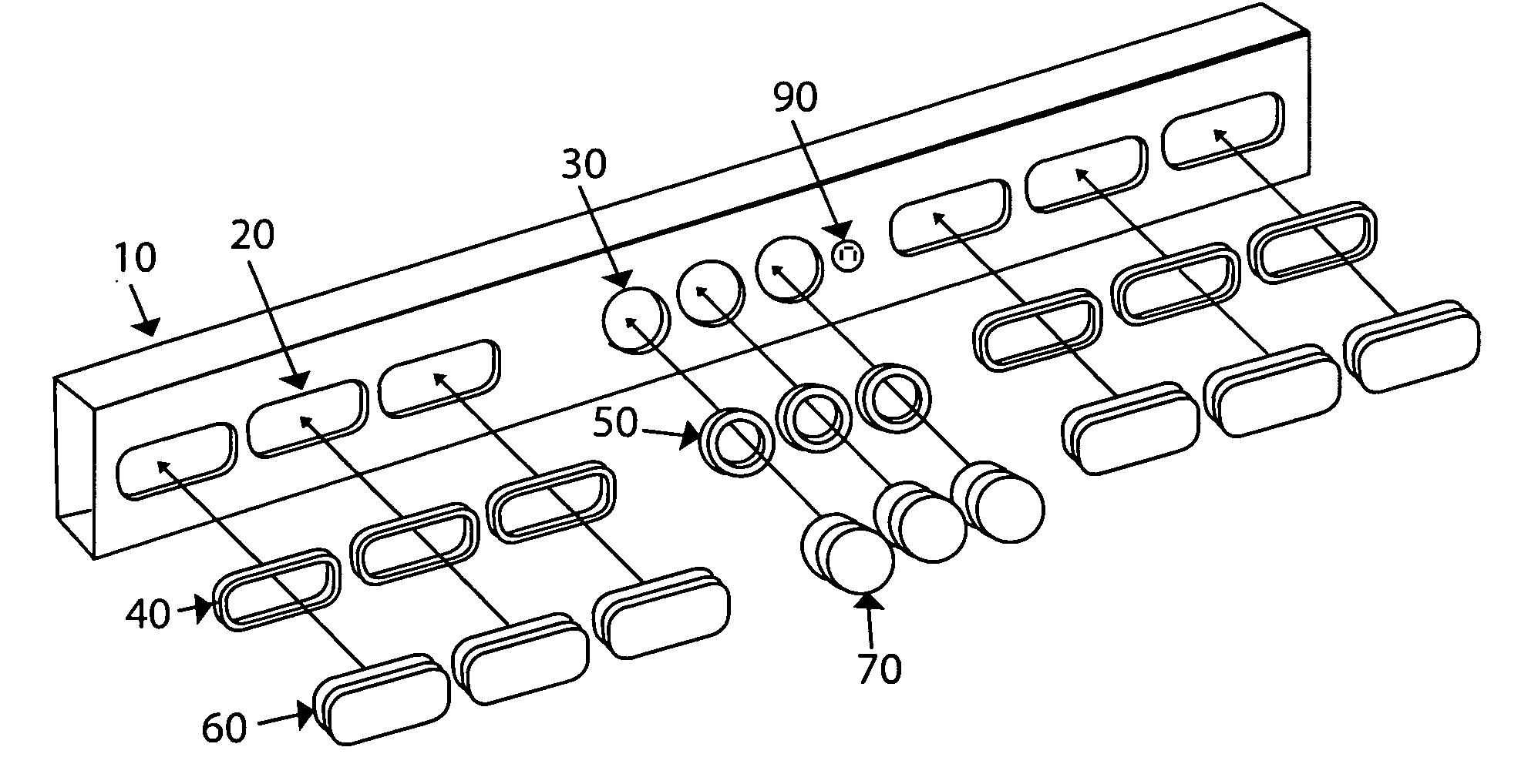
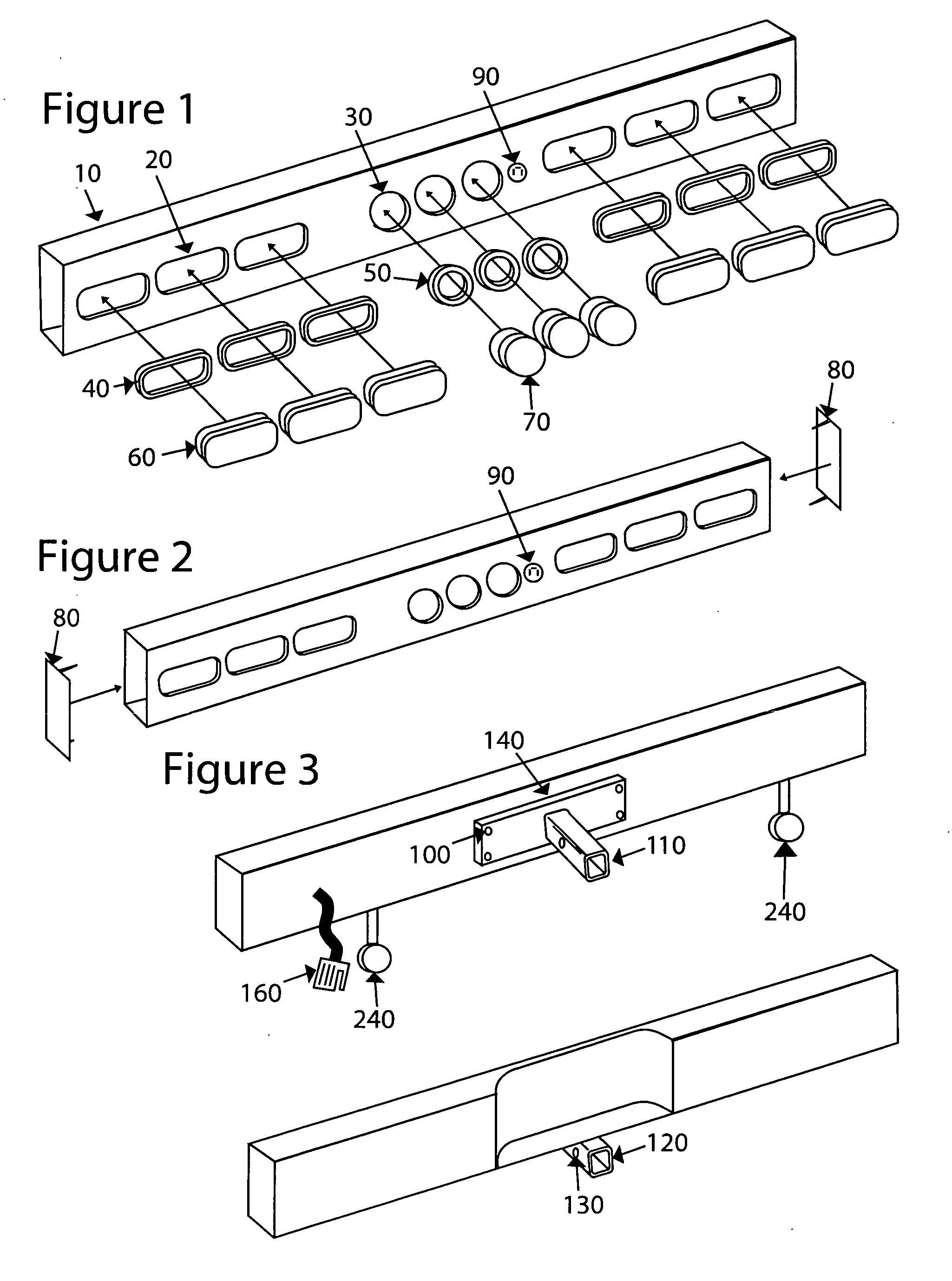
[0048] The present invention will hereinafter be described with reference to the accompanying drawings. In the drawings, the following reference numerals have been designated to identify their respective components. Specifically, Safety Light Bar Housing 10; Rectangular Lens Openings 20; Circular Lens Openings 30; Rectangular Mounting Flange 40; Circular Mounting Flange 50; Rectangular Lens and Lighting Fixture 60; Circular Lens and Lighting Fixture 70; Side End Caps 80; External Electrical Plug-In Socket 90; Back Plate Mounting Hole 100;

[0049] Male Tongue Insert 110; Female Receiving Socket 120; Pin Insertion Holes 130; Back Plate 140; Complete Light Fixture Assembly Unit 150 (having elements 60,70,160,270&40,50 encircling the unit); Generic Automobile Type Light 160; Wiring Harness Assembly 170; Plug Connectors 180; Wire Leads 190; Coupling Pin 200; Collar 210; Drain Hole 220; Bumper 230; Extension Bar 240; Protective Cover 250; Complete Light Bar Unit 260; Strobe Lights 270; Ele...


PUM


Abstract

The present invention relates to a full functioning safety light bar and signal assembly. A light system that utilizes a wiring harness assembly is further equipped with one or more of the following lights: driving, brake / signal, flasher / emergency, reverse, marker, strobe, fog or illuminating lights. Electric sensors in the body of the light bar unit control strobe and illuminating lights. The device compliments a vehicle by matching the various sizes, width and depth of their bumpers. Extension bars with the light fixture assembly can be attached to the light bar units to add greater illumination upon backing up and collars or strips of friction reducing materials are attached on the hitch components, e.g., such as the exterior of the male tongue insert and the interior cavities of the male tongue insert helping to limit vibration or noise. Locked protective covers keep the lights or lens in the light bar units from becoming scratched or damaged. Further, the ability to store an extra set of keys in a lockable security compartment is another safety feature provided with the safety light bar.

Description

CROSS-REFERENCE TO RELATED APPLICATIONS [0001] This application claims priority under 35 U.S.C. §119(e) of provisional application No. 60 / 520,299, filed Nov. 17, 2003, the entire contents of which are hereby incorporated by reference.BACKGROUND OF THE INVENTION [0002] 1. Field of the Invention [0003] The present invention relates to a safety light bar signal and assembly (light bar unit) that is an advancement in the devices that are connected into existing vehicle trailer hitches. The new system contains an integrated wiring harness assembly and connectors that operate a full functioning light bar unit. The present invention also includes a method of installing the new system on a variety of existing vehicle bumpers and hitch assemblies with the use of an expanding light bar housing capable of being sized for a variety of applications. [0004] 2. Description of the Background Art [0005] The background art illustrates a variety of trailer hitch lighting systems and decorative devices...

Claims


Application Information

Patent Timeline
IPC IPC(8): B60D1/60B60D1/62B60D1/64B60Q1/00B60Q1/30
CPCB60D1/60B60Q1/305B60D1/64B60D1/62
Inventor FRENCH, CRAIG
Owner GREAT LAKES MFG
Learn More