
Display device and driving method thereof

a display device and organic technology, applied in static indicating devices, solid-state devices, instruments, etc., can solve the problems of reduced area of each pixel, reduced yield, and reduced circuit structure of pixels, so as to improve aperture ratio and yield, simplify pixel structure and wiring, and prevent rc delay and voltage drop

Active Publication Date: 2005-05-19
SAMSUNG DISPLAY CO LTD
View PDF5 Cites 33 Cited by
  • Summary
  • Abstract
  • Description
  • Claims
  • Application Information

AI Technical Summary

Benefits of technology

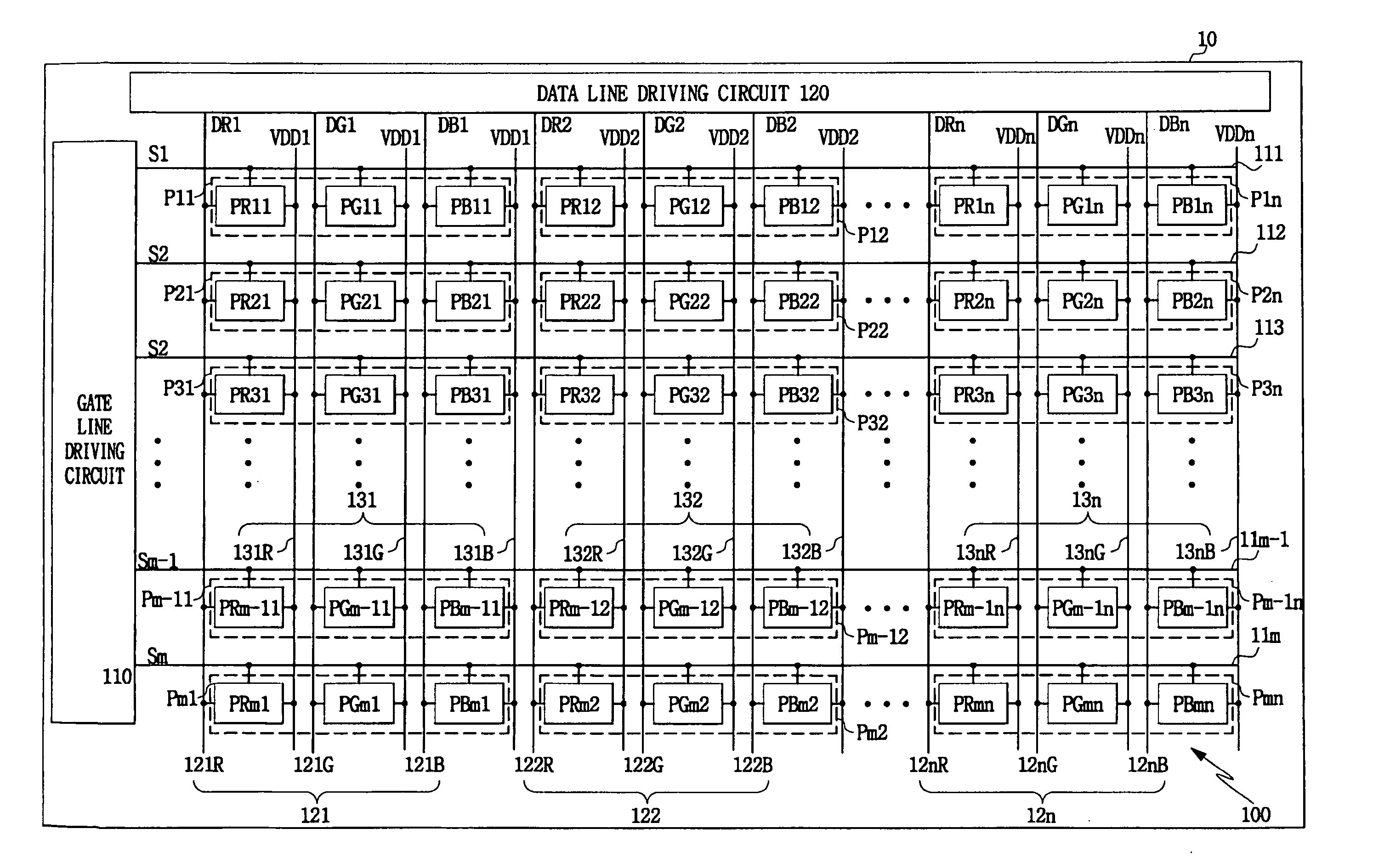
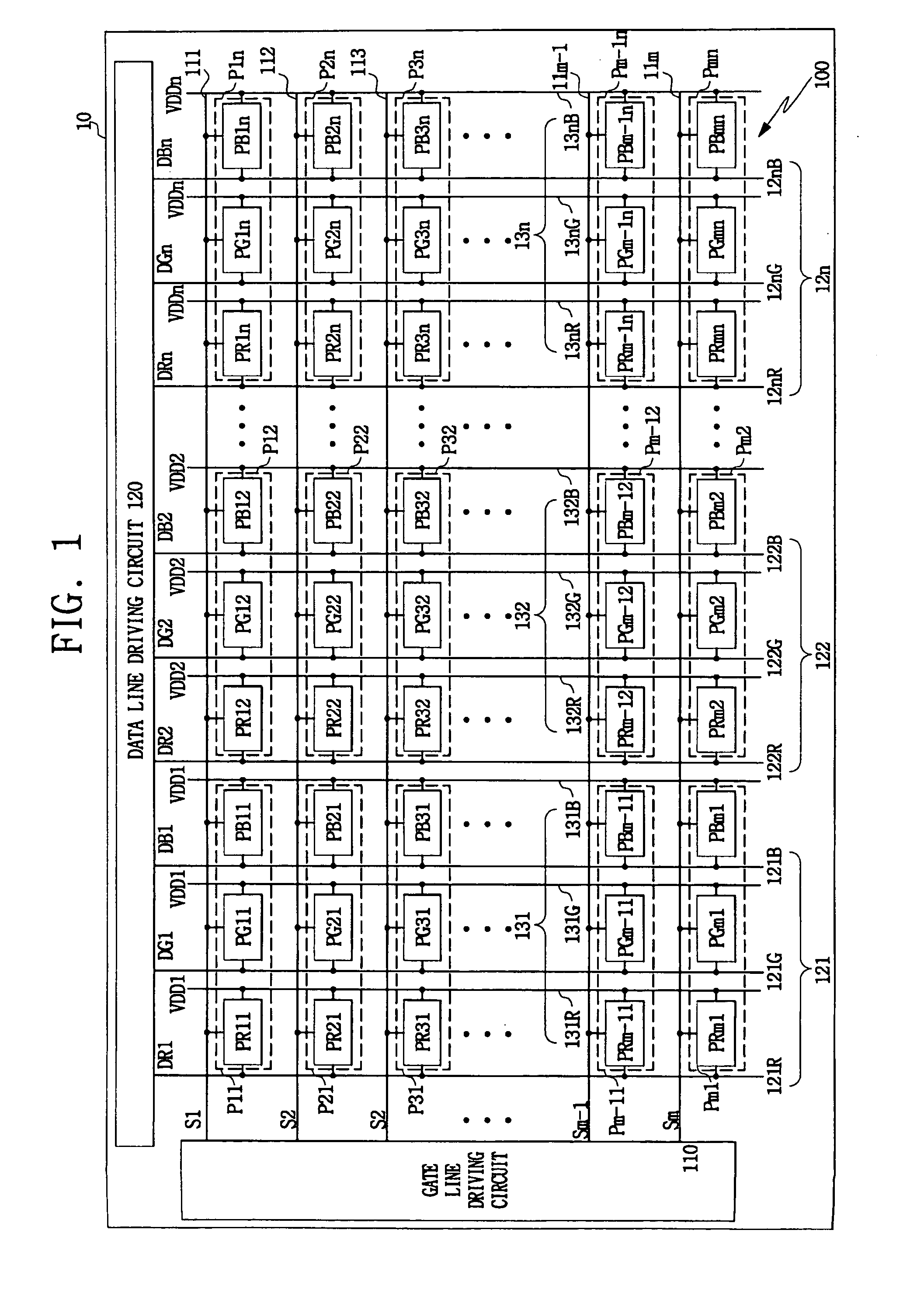
[0030] In one exemplary embodiment of the present invention, is provided a pixel circuit of an organic electroluminescent display device capable of improving aperture ratio and yield and a driving method for the pixel circuit of the organic electroluminescent display device.
[0031] In one exemplary embodiment of the present invention, is provided a pixel circuit of an organic electroluminescent display device capable of preventing RC delay and voltage drop and a driving method for the pixel circuit of the organic electroluminescent display device.
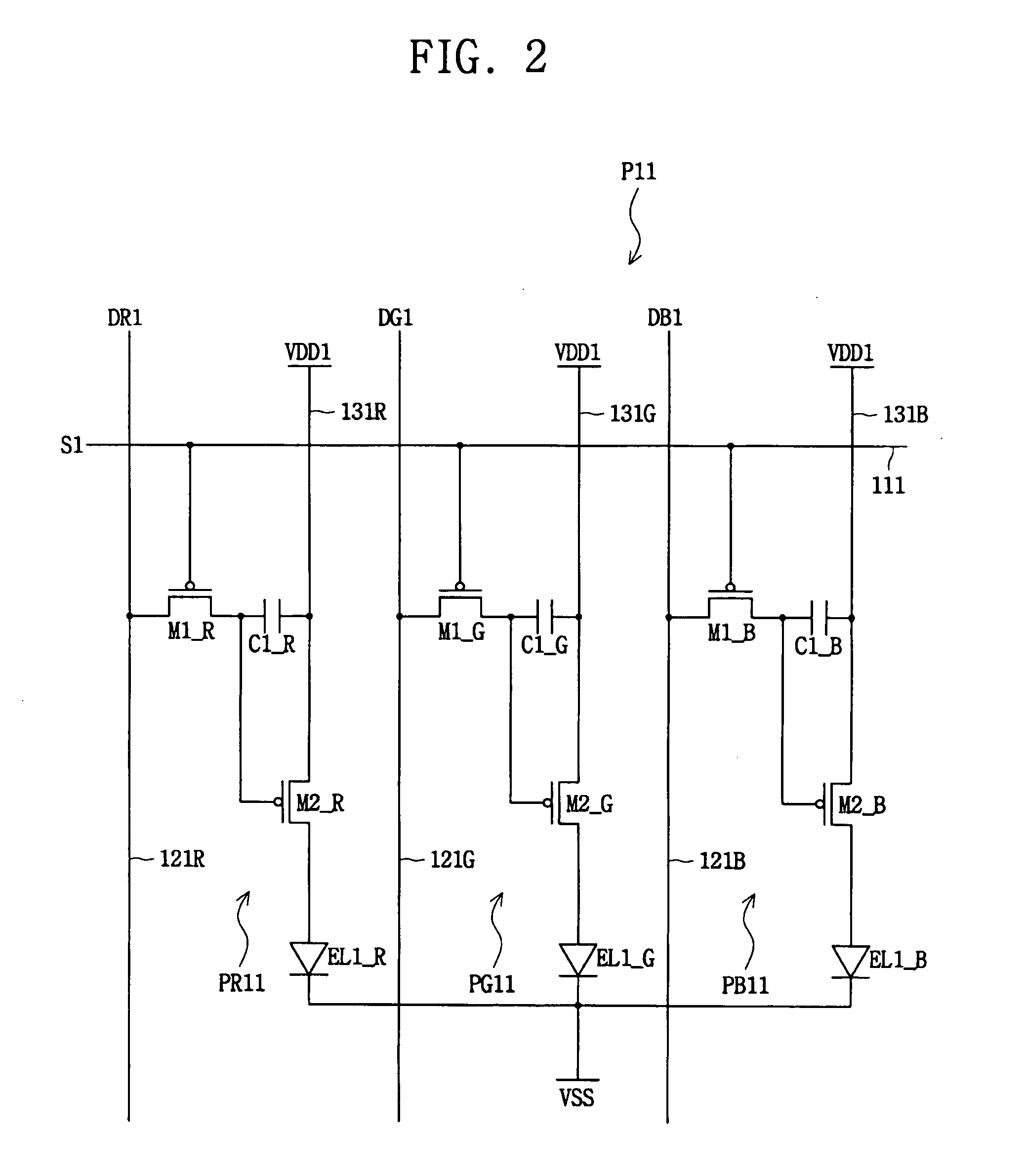
[0032] In one exemplary embodiment of the present invention, is provided a pixel circuit of an organic electroluminescent display device capable of simplifying pixel structure and wiring by driving one pixel through one driving element and a driving method of the pixel circuit of the organic electroluminescent display device.
[0033] In one exemplary embodiment of the present invention, is provided an organic electroluminescent display device having a simplified circuit structure and wiring by reducing the number of emission control lines and a driving method of the organic electroluminescent display device.

Problems solved by technology

Therefore, the circuit structure for the pixels in a conventional organic electroluminescent display device is complicated as a plurality of wirings and a plurality of elements are arranged per each pixel, and yield is reduced as probability of generating defects is increased accordingly.
Further, the area of each pixel is reduced as the resolution of the display device is being increased, and not only is it difficult to arrange many elements on one pixel, but also the aperture ratio is reduced accordingly.

Method used


Image

  • Display device and driving method thereof
  • Display device and driving method thereof
  • Display device and driving method thereof

Examples


Embodiment Construction

[0066] The present invention will now be described in detail in connection with certain exemplary embodiments with reference to the accompanying drawings. In the drawings, like reference numerals / characters designate like elements.

[0067]FIG. 4 illustrates a block structural view of an organic electroluminescent display device according to a first exemplary embodiment of the present invention.

[0068] Referring to FIG. 4, an organic electroluminescent display device 50 according to the first exemplary embodiment includes a pixel part 500, a gate line driving circuit 510, a data line driving circuit 520 and an emission control signal generating circuit 590. The gate line driving circuit 510 sequentially generates scan signals S1′˜Sm′ to gate lines of the pixel part 500 during one frame. The data line driving circuit 520 sequentially supplies red, green and blue data signals D1′˜Dn′ to data lines of the pixel part 500 whenever scan signals are applied during one frame. The emission con...


PUM


Abstract

A pixel circuit of display device for realizing a certain color during a display period of time comprising. The pixel circuit includes at least two light emitting elements, each said light emitting element for emitting a corresponding one of colors during the display period of time. An active element is commonly connected to the at least two light emitting elements to drive the at least two light emitting elements in response to at least one emission control signal. The active element time-divisionally drives the at least two light emitting elements using the at least one emission control signal during the display period of time per a sub display period of time. The at least two light emitting elements realize the certain color in the display period of time by time-divisionally emitting the corresponding ones of the colors, one of the corresponding ones of the colors being emitted per the sub display period of time.

Description

CROSS REFERENCE TO RELATED APPLICATIONS [0001] This application claims priority to and the benefit of Korean Patent Application No. 2003-80739, filed on Nov. 14, 2003 in the Korean Intellectual Property Office, the disclosure of which is incorporated herein by reference in its entirety. This application contains subject matter related to the subject matter disclosed in a commonly owned, co-pending U.S. patent application Ser. No. ______ (Attorney Docket No. 52704 / DBP / S1082) entitled “Display Device and Driving Method Thereof,” filed on even date herewith.BACKGROUND OF THE INVENTION [0002] 1. Field of the Invention [0003] The present invention relates to a self-emissive organic display device, and more particularly, to a sequential driving type organic electroluminescent display device in which red, green and blue light emitting elements are time-divisionally driven by one driving element and a driving method of the sequential driving type organic electroluminescent display device. [...

Claims


Application Information

Patent Timeline
Patent Type & Authority Applications(United States)
IPC IPC(8): G09G3/20H01L51/50G09G3/22G09G3/291G09G3/296G09G3/30G09G3/32
CPCG09G3/2022G09G3/3233G09G2300/0465G09G2300/0814G09G2320/043G09G2300/0861G09G2300/0866G09G2310/0235G09G2310/06G09G2300/0842G09G2300/0804G09G3/30
Inventor KWAK, WON-KYU
Owner SAMSUNG DISPLAY CO LTD
Learn More