Pneumatic tire

a technology of pneumatic tires and tires, applied in the field of pneumatic tires, can solve the problems of reducing the speed rating of tires, affecting the normal operation of tires, reducing the capability of tires, etc., and achieves the effects of improving the durability of tires, reducing pressure, and improving speed performan

Inactive Publication Date: 2005-05-19
THE GOODYEAR TIRE & RUBBER CO
View PDF8 Cites 2 Cited by
  • Summary
  • Abstract
  • Description
  • Claims
  • Application Information

AI Technical Summary

Benefits of technology

[0005] One aspect of the invention is directed to achieving an improved speed performance and improved durability of a tire. Another aspect of the invention is directed to the conflicting goals of a run-flat tire with high speed capability, thus providing persons with high performance vehicles with the desired full inflation performance expected and demanded from their vehicle and with assurance that the tire will continue to perform in atypical reduced pressure situations.

Problems solved by technology

The increased sidewall thickness, achieved by the use of additional rubber layers in the sidewall, can reduce a tires speed rating because of the greater weight and internal heat generated by the tire.
Thus, the need to have a run-flat tire also affects the normal operation of the tire by reducing the tire's capability.

Method used


Image

  • Pneumatic tire
  • Pneumatic tire

Examples


Embodiment Construction

[0037] The following language is of the best presently contemplated mode or modes of carrying out the invention. This description is made for the purpose of illustrating the general principles of the invention and should not be taken in a limiting sense. The scope of the invention is best determined by reference to the appended claims.

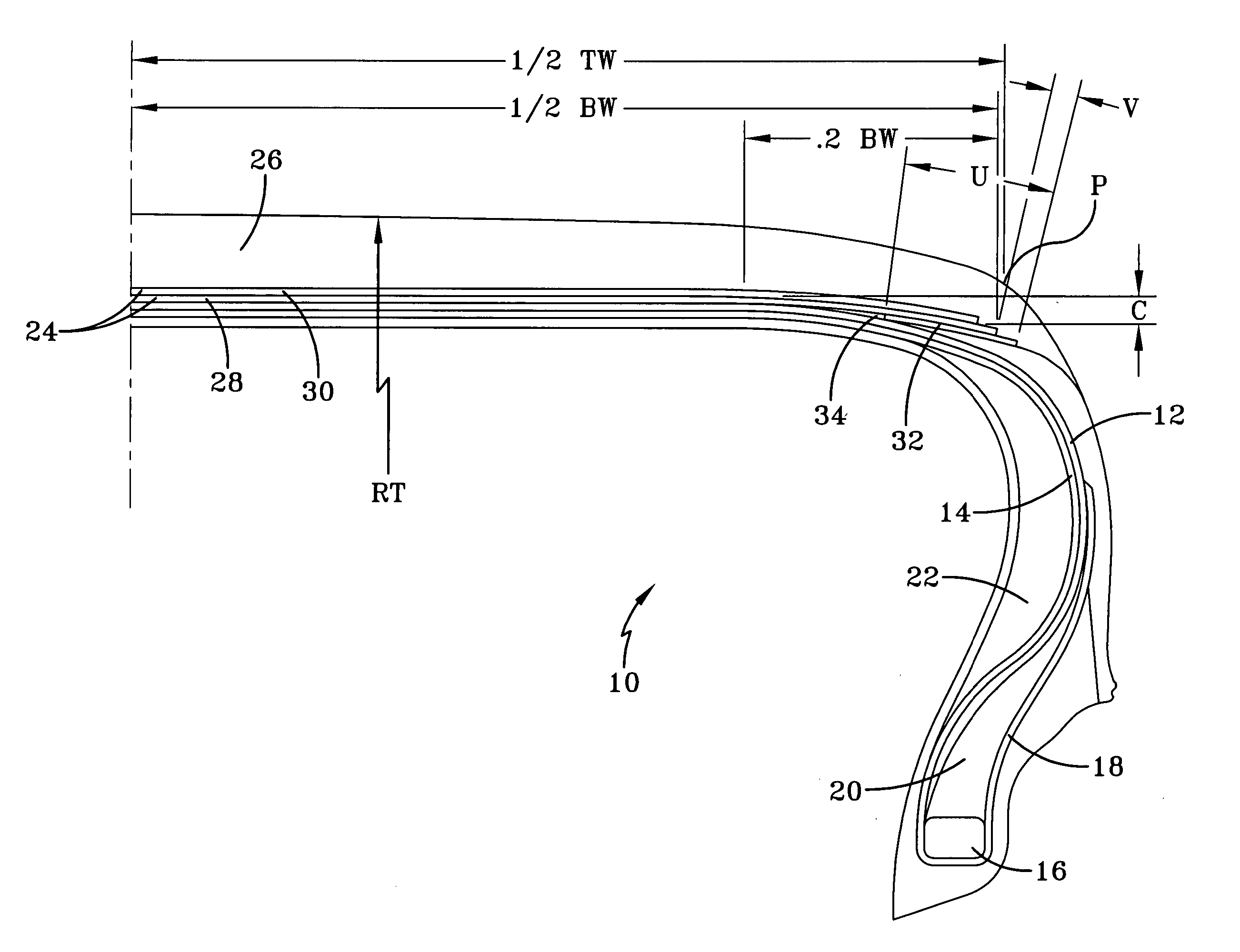
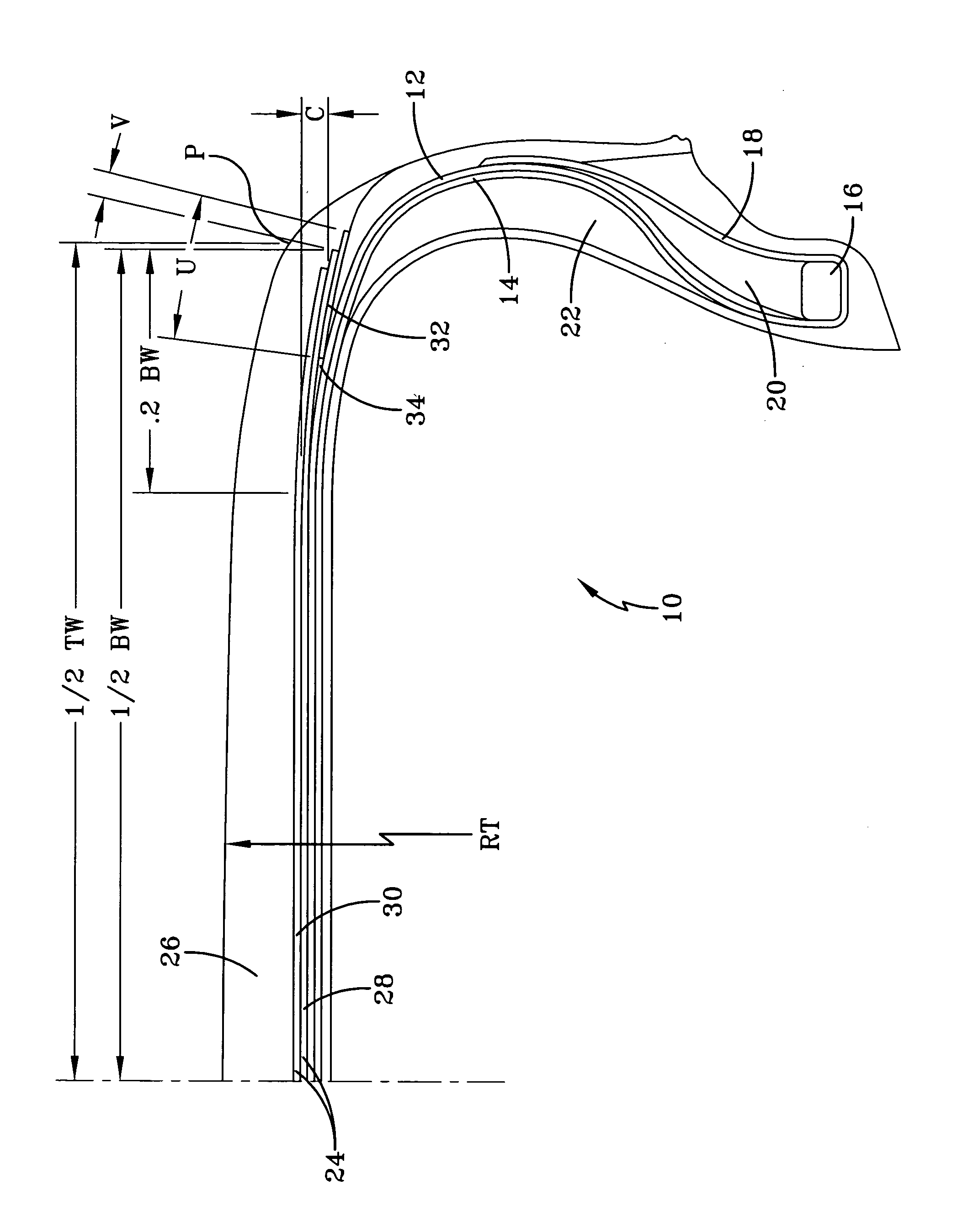
[0038] Based on conventional manufacturing sequences, there are two basic parts of pneumatic radial ply tires used on cars and trucks. One part is the carcass, typically assembled on a cylindrical building drum prior to expansion. The carcass includes the reinforcing plies, two inextensible annular beads, sidewalls, the innerliner, and the elastomeric material that holds those components together after the tire is assembled and the carcass is cured. The other part of the tire is the crown, which is assembled separately from the carcass and includes the tread and the underlying belts or breakers, also held together by a matrix of cured rubber. The carc...


PUM


Abstract

A pneumatic tire has a tread with shoulders, a belt structure located below the tread, and a carcass with two sidewalls, two inextensible annular beads, and a radial ply structure. The shoulders of the tire have a continuous curving radially outer profile so that the shoulders transition smoothly from the tread profile to the tire sidewalls; ideally, the locus of the radii defining the shoulder are located on the inner side of the tire. The tire has a belt structure formed of an annular layer of parallel cords directly adjacent to the radial ply structure, the annular layer having a pair of opposing annular edges and a continuous radius curve profile. Located radially inward of the axial edges of the annular layer of the belt structure is an annular reinforcing strip layer. The strip has a width of not greater than 30 mm and extends axially outward of the annular layer edges by a distance of not more than 10 mm.

Description

FIELD OF THE INVENTION [0001] The present invention is directed to a pneumatic tire. More specifically, the present invention is directed to a belt structure underlying the tire tread improves the tire's performance characteristics for passenger and light truck tires. BACKGROUND OF THE INVENTION [0002] Almost all pneumatic tires are given a speed rating based on the maximum speed capability of the tire. The speed rating in conventional use today was developed in response to the need to control the safe performance of tires at standardized speeds. When a vehicle manufacturer specifies tires, the required speed rating for the tire is dictated by the type of vehicle. For a family type sedan car, the speed rating of a tire will likely be lower than the speed rating for a high performance sports car. Current speed ratings begin at 50 km / h, a B speed rating, and go to a Y or ZR speed rating for tires capable of 300 km / h and above. The majority of passenger tires have a speed rating of eit...

Claims


Application Information

Patent Timeline
Patent Type & Authority Applications(United States)
IPC IPC(8): B60C9/20B60C9/22B60C17/00
CPCB60C9/20B60C9/22Y10T152/10765Y10T152/10783B60C17/0009
Inventor BARAN, WOICIECH FRANCISZEK
Owner THE GOODYEAR TIRE & RUBBER CO
Why Eureka
Try Eureka