
System and method for stabilizing landslides and steep slopes

Inactive Publication Date: 2005-05-19
CARTE JOSEPH D +1
View PDF19 Cites 17 Cited by
  • Summary
  • Abstract
  • Description
  • Claims
  • Application Information

AI Technical Summary

Benefits of technology

[0015] The structural members of the present invention are easily installable at remote locations. The soil stabilization system of the present requires little or no land area greater than the land area of the landslide or steep slope itself. However, additional area may be advantageously utilized, if desired.
[0036] At least one gusset is preferably formed to the two plates, so as to enhance a structural strength of the soil bolting device.

Problems solved by technology

Downhill soil movement, such as that which occurs during landslides and ground creep, can cause substantial damage to various structures such as buildings, highways and railroads.
Such damage can have severe economic consequences.
However, where structures are involved or where space limitations prevent the use of excavation equipment, then in-place stabilization is generally required.
To date, the practice of in-place slope stabilization has generally been limited to the use of retaining walls, buttresses, pilings, and soil nailing techniques.
The stem of a retaining wall is cantilevered from the foundation and is at a substantial mechanical disadvantage with respect to undesirable potential movement.
Thus, such retaining walls typically require an extensive foundation in order to adequately resist failure.
Excavation of soil for an extensive foundation at the base (or toe) of a landslide can remove the precarious support presently available and thus inadvertently mobilize the slide.
However, expense and space limitations sometimes preclude this option.
Both MSE walls and buttresses require significant space and a stable foundation at the toe of the landslide.
However, piling and drill piers are relatively costly and require large and expensive installation equipment.
However, expense sometimes preclude this option.
Soil nailing requires a considerable understanding of soil mechanics and the engineering uncertainty of the magnitudes of the shear resistance around the rods makes design difficult.
Although empirical designs have been somewhat successful, such designs are generally undesirable because they do not typically have a known factor of safety.
Consequently, this method also suffers from the engineering uncertainties associated with quantifying the magnitude of the resulting increase in shear strength.
As such, although the prior art has recognized, to a limited extent, the problem of undesirable soil movement, the proposed solutions have, to date, been ineffective in providing a satisfactory remedy wherein space limitations exists.

Method used


Image

  • System and method for stabilizing landslides and steep slopes
  • System and method for stabilizing landslides and steep slopes
  • System and method for stabilizing landslides and steep slopes

Examples


Embodiment Construction

[0053] Many alterations and modifications may be made by those having ordinary skill in the art without departing from the spirit and scope of the invention. Therefore, it must be understood that the illustrated embodiment has been set forth only for the purposes of example and that it should not be taken as limiting the invention as defined by the following claims. For example, notwithstanding the fact that the elements of a claim are set forth below in a certain combination, it must be expressly understood that the invention includes other combinations of fewer, more or different elements, which are disclosed herein even when not initially claimed in such combinations.

[0054] The words used in this specification to describe the invention and its various embodiments are to be understood not only in the sense of their commonly defined meanings, but to include by special definition in this specification structure, material or acts beyond the scope of the commonly defined meanings. Th...


PUM


Abstract

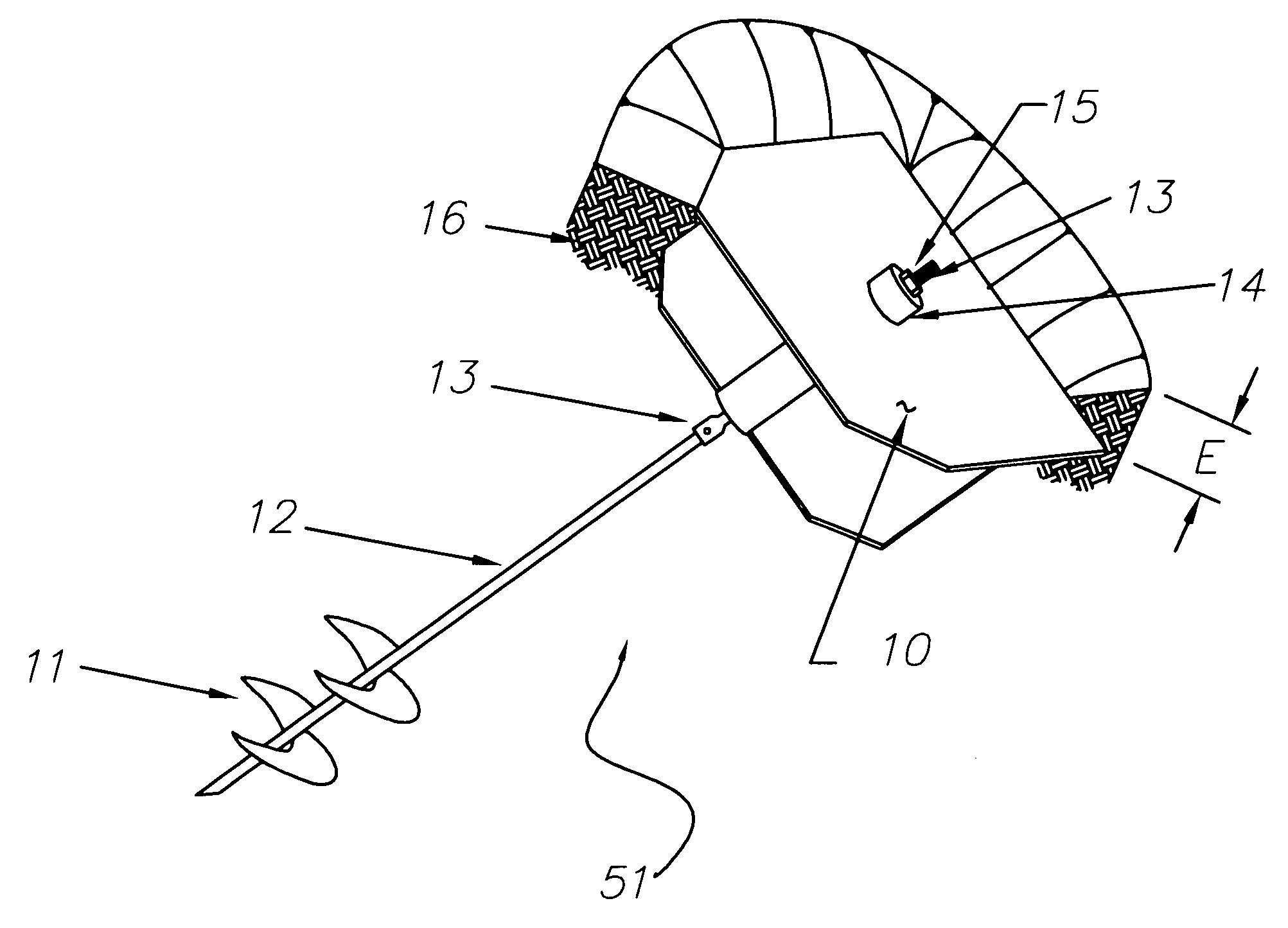
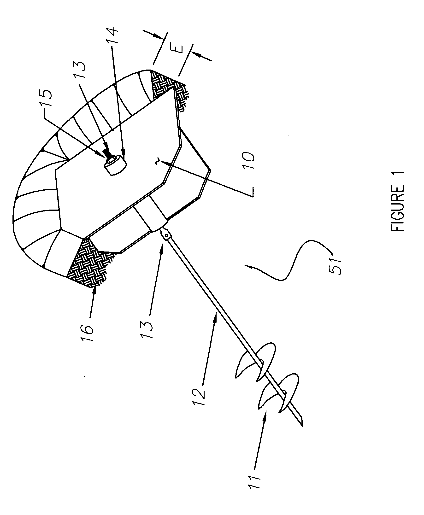
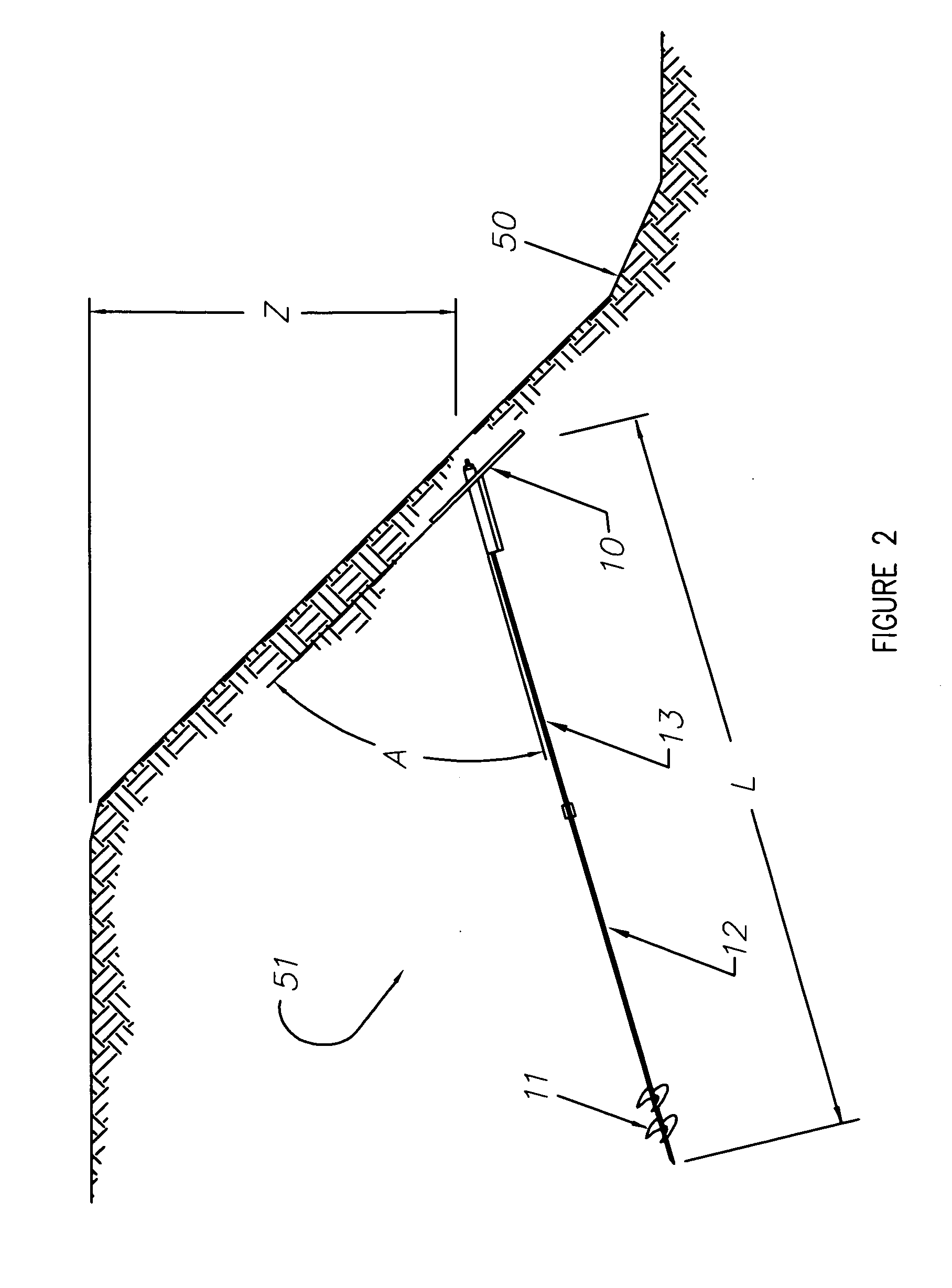
A method for stabilizing soil so as to inhibit undesirable movement thereof includes placing at least one anchor, such as a self-advancing helical anchor or a rock anchor, in the ground and then attaching a soil bolting device to the anchor. The soil bolting device may then be moved toward the anchor, such as by tightening a fastener which attaches the soil bolting device to the anchor, so as to compact and stabilize soil proximate the soil bolting device.

Description

PRIORITY CLAIM [0001] This patent application claims the benefit of the priority date of U.S. Provisional Patent Application Ser. No. 60 / 523,045 filed on Nov. 17, 2003 and entitled SOIL BOLTING: A SYSTEM OF DEVISES AND METHOD FOR STABILIZING LANDSLIDES AND STEEP SLOPES (Rutan & Tucker docket no. 101110.0001PRO) pursuant to 35 USC 119, the entire contents of which are hereby expressly incorporated by reference.FIELD OF THE INVENTION [0002] The present invention relates generally to soil stabilization. The present invention relates more particularly to a system and method for stabilizing landsides, steep slopes, and the like, wherein at least one anchor is placed into the ground and a soil bolting device is attached to the anchor. BACKGROUND OF THE INVENTION [0003] Downhill soil movement, such as that which occurs during landslides and ground creep, can cause substantial damage to various structures such as buildings, highways and railroads. Such damage can have severe economic conseq...

Claims


Application Information

Patent Timeline
IPC IPC(8): E02D17/20
CPCE02D17/207Y02A10/23
Inventor CARTE, JOSEPH D.KNIGHT, JOHN R.
Owner CARTE JOSEPH D
Learn More