Broadband surge protector with non-resetting current limiter

a surge protector and wideband technology, applied in the direction of emergency protective arrangements for limiting excess voltage/current, spark gap details, and arrangements responsive to excess voltage, can solve the problems of resistors such as such size and insufficient surge toleran

Inactive Publication Date: 2005-05-12
BOURNS INC
View PDF55 Cites 18 Cited by
  • Summary
  • Abstract
  • Description
  • Claims
  • Application Information

AI Technical Summary

Benefits of technology

[0014] In a specific preferred embodiment of the invention, the first and second resistive elements are carbon film resistors that are physically small enough to create sufficient localized ohmic (I2R) heating to actuate the thermally-responsive sneak current-grounding switches so that they switch from their normal position to their tripped position, as described above. Resistors of such size, however, may not be sufficiently surge-tolerant for the applications in which the surge protection device is likely to be employed. To this end, the surge suppression elements are conn

Problems solved by technology

Resistors of such size, however, may not be sufficiently surge-tolerant for the applications in which the surge protection device is likely to be employed.

Method used


Image

  • Broadband surge protector with non-resetting current limiter
  • Broadband surge protector with non-resetting current limiter
  • Broadband surge protector with non-resetting current limiter

Examples


Embodiment Construction

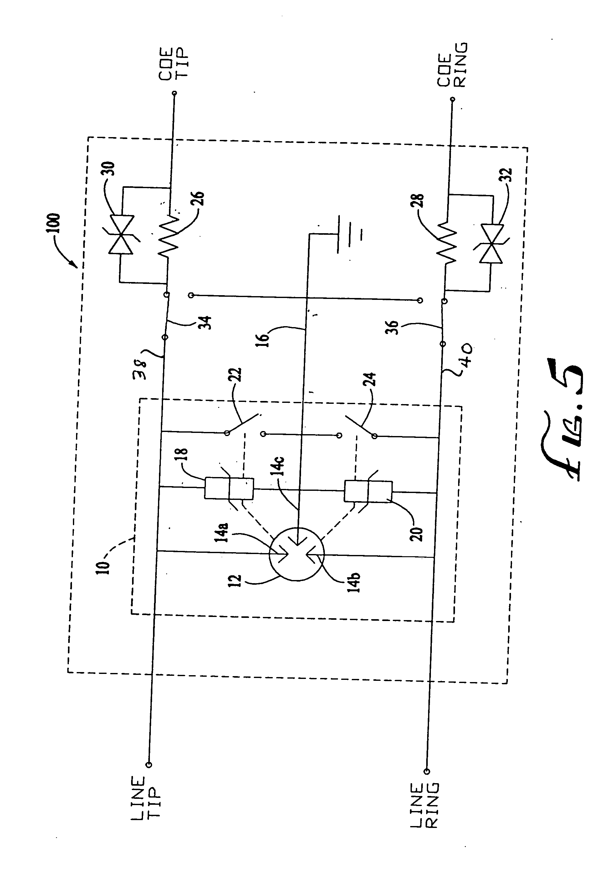
[0021] Referring first to FIG. 5, a surge protection device 100 with sneak current protection, in accordance with a preferred embodiment of the present invention, is shown connected between the Tip and Ring lines of a typical telecommunications subscriber line interface circuit (“SLIC”). The device of the invention includes a multi-stage surge protector 10, as described in U.S. Pat. No. 6,327,129—Oertel et al., the disclosure of which is incorporated herein by reference. Briefly described, the surge protector 10 comprises a gas discharge tube (“GDT”) 12 having three electrodes, 14a, 14b, 14c, the first of which is connected to the Tip line, the second of which is connected to the Ring line, and the third of which is connected to a ground line 16. A first metal oxide varistor (“MOV”) 18 is connected between the Tip line and the ground line 16, and a second MOV 20 is connected between the Ring line and the ground line 16. In a specific embodiment of the invention, the GDT 12 has break...


PUM


Abstract

A surge protection device includes a gas discharge tube surge protector connected between a Tip line and a Ring line, and further includes solid state heat-generating resistive elements in the Tip and Ring lines, and thermally-responsive sneak current grounding switches in the Tip and Ring lines that have an untripped position connecting Tip and Ring line terminals of the surge protector respectively to the Tip and Ring line resistive elements, and a tripped position in which they ground the Tip and Ring line terminals. The switches are switched to their tripped position in response to the heat generated in the resistive elements as a consequence of current passing through them that exceeds a predetermined current level. A surge suppression element is connected in parallel with each of the resistive elements. The resistive elements are preferably carbon film resistors, and the surge suppression elements are preferably transient voltage suppression diodes.

Description

CROSS-REFERENCE TO RELATED APPLICATION [0001] Not Applicable FEDERALLY SPONSORED RESEARCH OR DEVELOPMENT [0002] Not Applicable BACKGROUND OF THE INVENTION [0003] The present invention is directed to an electrical surge protection device of the type used to protect equipment and electrical circuits from being damaged by overvoltage surges and / or overcurrent surges. [0004] Surge protection devices may be used to protect power lines, communication lines, and electrical equipment connected to power lines and communication lines from overvoltage surges, such as may be caused by lightning or power line cross conditions, for example. A power line cross condition, which may be caused by a downed power line, consists of an excessive voltage and an alternating current (typically 60 Hz) of excessive amplitude. Overcurrent conditions can result from induced currents from nearby power lines [0005] During an overvoltage surge, a surge protection device may provide temporary surge protection by sh...

Claims


Application Information

Patent Timeline
IPC IPC(8): H01T1/14H02H9/06H04M3/18
CPCH01T1/14H04M2201/80H04M3/18H02H9/06Y02A30/00
Inventor MARTIN, DAVIDDIETZSCH, CURTIS
Owner BOURNS INC
Why Eureka
Try Eureka