
Airbag cushion with angled recess

a technology of airbag cushion and recess, which is applied in the direction of pedestrian/occupant safety arrangement, vehicular safety arrangement, vehicle components, etc., can solve the problems of fatal injuries to passengers, occupant injuries, and airbag deployment that does not leave a sufficiently safe distance between the airbag contact surface, etc., to increase the inner pressure of the recess, reduce the moving distance of the occupant before the occupant stops, and increase the energy absorption effect of the right and left side portions

Inactive Publication Date: 2005-05-12
TAKATA CORPORATION
View PDF18 Cites 62 Cited by
  • Summary
  • Abstract
  • Description
  • Claims
  • Application Information

AI Technical Summary

Benefits of technology

The present invention provides an airbag device that includes an airbag that can be inflated and deployed in an emergency situation. The airbag has a recess that maintains its shape when pressure is applied to the right and left side portions. The recess increases the energy absorption effect and reduces the need for an increased output of the inflator. The airbag also has a front surface that projects towards the occupant, allowing for more efficient restraint of the occupant's head during the initial stages of impact. Overall, the airbag device provides improved safety and protection for vehicle occupants in the event of an emergency.

Problems solved by technology

In conventional airbag devices, the airbag when deployed does not leave a sufficiently safe distance between the airbag contact surface and the vehicle occupant.
Thus, in a vehicle emergency the kinetic energy of the occupant is not efficiently absorbed by the airbag, which may result in injury to the occupant.
As a result, some passengers, especially children, have been fatally injured.
Another disadvantage of conventional airbags is that the restraint force of the airbag is not focused on the mass point of the occupant's head.
Thus, the kinetic energy of the occupant's head is not efficiently absorbed.

Method used


Image

  • Airbag cushion with angled recess
  • Airbag cushion with angled recess
  • Airbag cushion with angled recess

Examples


Embodiment Construction

[0031] Embodiments according to the present invention will be described with reference to the attached drawings. In the description below, the longitudinal direction is identical to that of a vehicle in which the head-protecting airbag is mounted. Although the following embodiments are directed to an airbag device for a passenger seat mounted in the upper part of a vehicle dashboard, the airbag device according to the present invention may be applied to an airbag other than for a passenger seat.

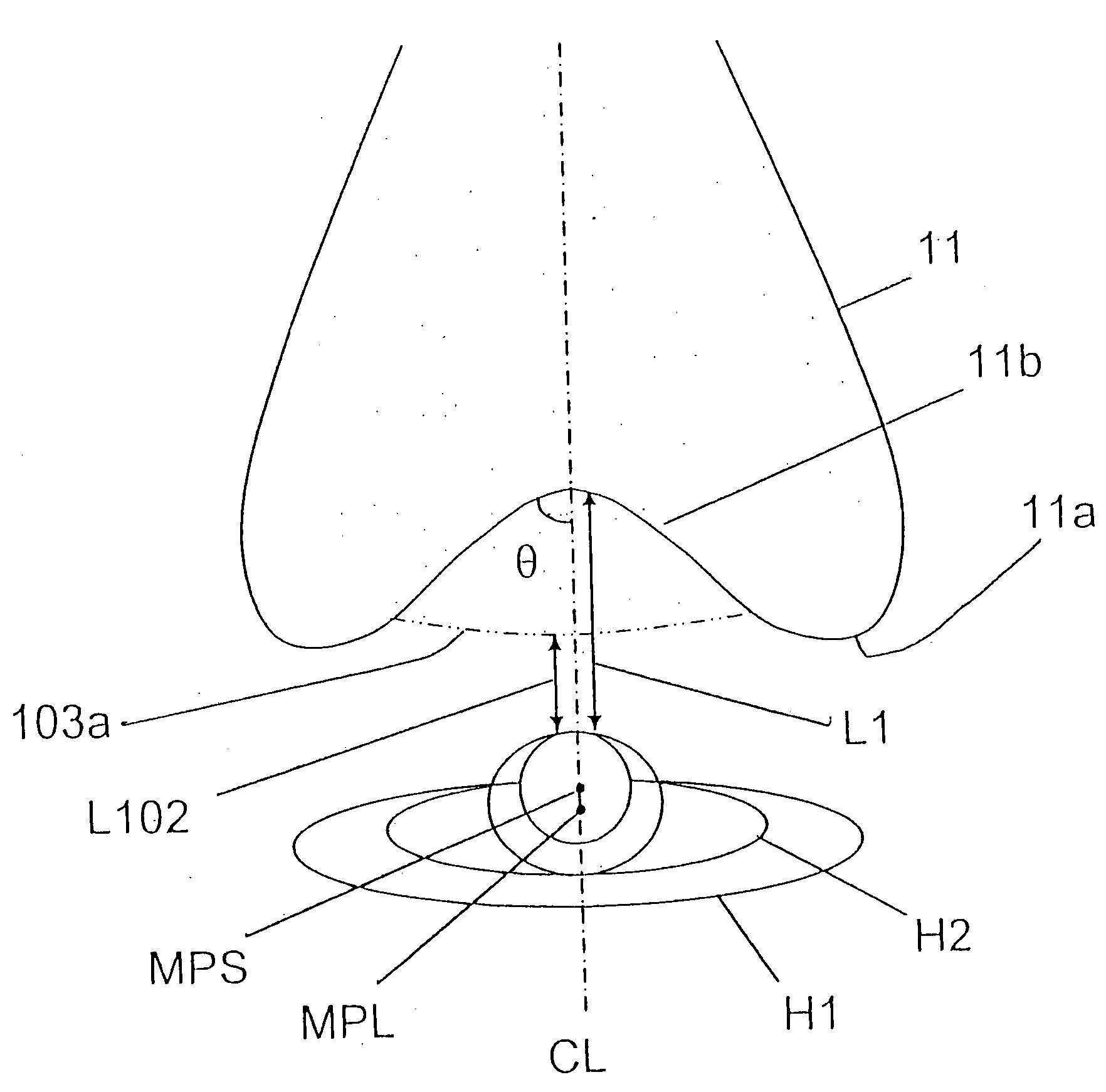
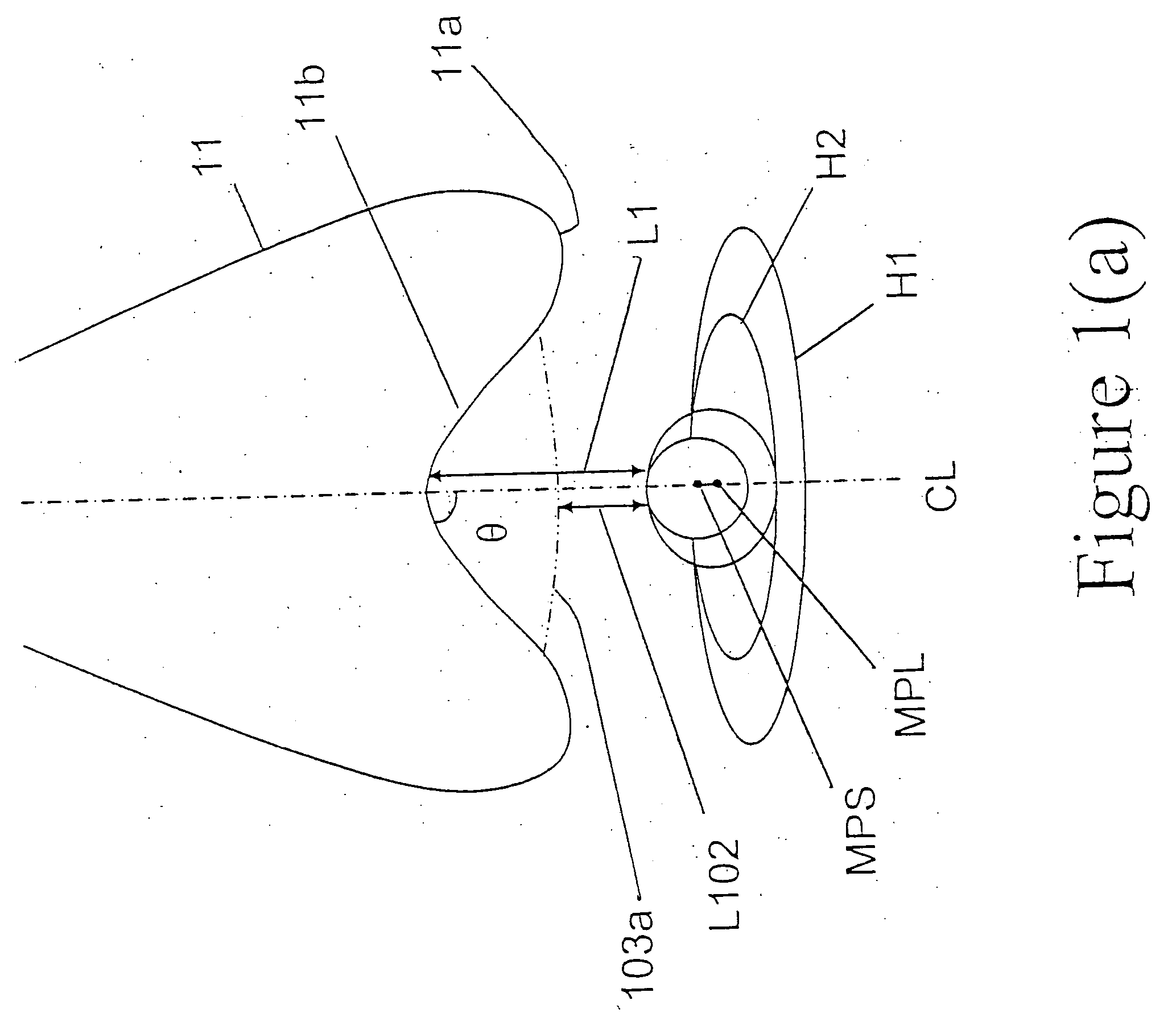
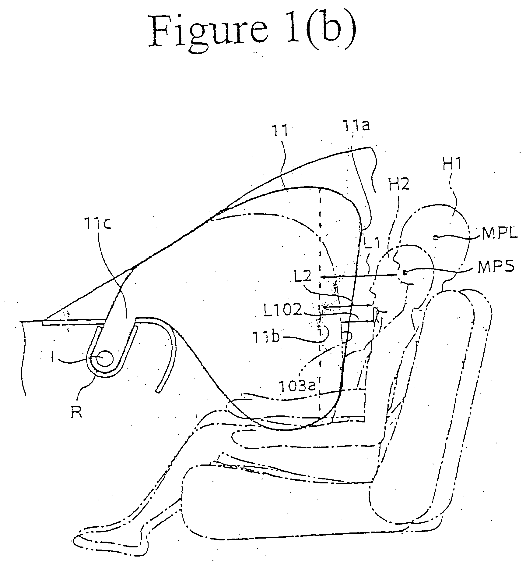
[0032] According to an embodiment of the present invention, an airbag device is provided. The airbag device includes an airbag that is normally stored in an upper part of an instrument panel. The airbag can be inflated and deployed into a space in front of a vehicle occupant in the event of an emergency, such as a vehicle collision. In a top view, the airbag upon completion of deployment has a right side portion, a left side portion, and a recess formed between the right and left side portio...


PUM


Abstract

An airbag device with an improved airbag configuration to protect a vehicle occupant more efficiently. The airbag device is stored in the upper portion of an instrument panel of a vehicle under normal situations. The airbag device has an airbag that is deployable into a space in front of a vehicle occupant in the event of a vehicle emergency, such as a collision. The airbag viewed from the top when fully deployed and inflated has a right side portion, a left side portion, and a recess between the right and left side portions. When pressure is applied to the right and left side portions, the recess maintains a recessed shape.

Description

BACKGROUND OF THE INVENTION [0001] This application claims the benefit of Provisional Application No. 60 / 517,921, filed Nov. 7, 2003[0002] The present invention relates to an airbag device in which an airbag is inflated to protect a vehicle occupant in the event of a vehicle collision. More particularly, the present invention relates to an airbag device with an improved airbag configuration for protecting an occupant more efficiently. [0003] An airbag for protecting a vehicle occupant is normally stored in a folded state in a cavity disposed in the middle section of a steering wheel or within an instrument panel of a vehicle. In the event of a vehicle collision, the airbag is deployed and inflated in the vehicle interior by gas produced by an inflator. The inflated airbag receives and restrains the occupant. [0004] In conventional airbag devices, the airbag when deployed does not leave a sufficiently safe distance between the airbag contact surface and the vehicle occupant. Thus, in...

Claims


Application Information

Patent Timeline
Patent Type & Authority Applications(United States)
IPC IPC(8): B60R21/16B60R21/20B60R21/231B60R21/233B60R21/2338
CPCB60R21/231B60R21/233B60R2021/23386B60R2021/23107B60R2021/23382B60R21/2338
Inventor MATSUMURA, SHINZO
Owner TAKATA CORPORATION
Learn More