Integrated light source and optical waveguide and method

Inactive Publication Date: 2005-05-05
GAO JU
View PDF8 Cites 15 Cited by
  • Summary
  • Abstract
  • Description
  • Claims
  • Application Information

AI Technical Summary

Problems solved by technology

In a conventional system, the coupler is a reflector shaped to change the direction of incident light rays, and the complexity thereof has limited the effectiveness of distributed light systems.

Method used


Image

  • Integrated light source and optical waveguide and method
  • Integrated light source and optical waveguide and method
  • Integrated light source and optical waveguide and method

Examples


Embodiment Construction

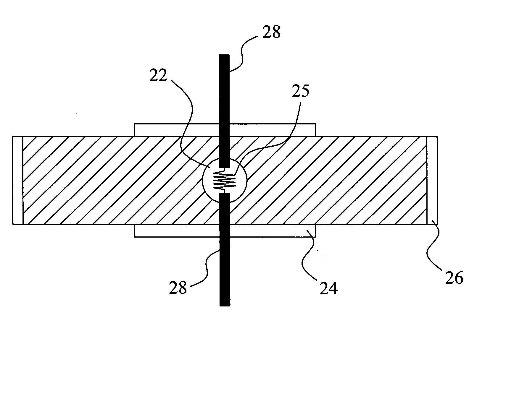
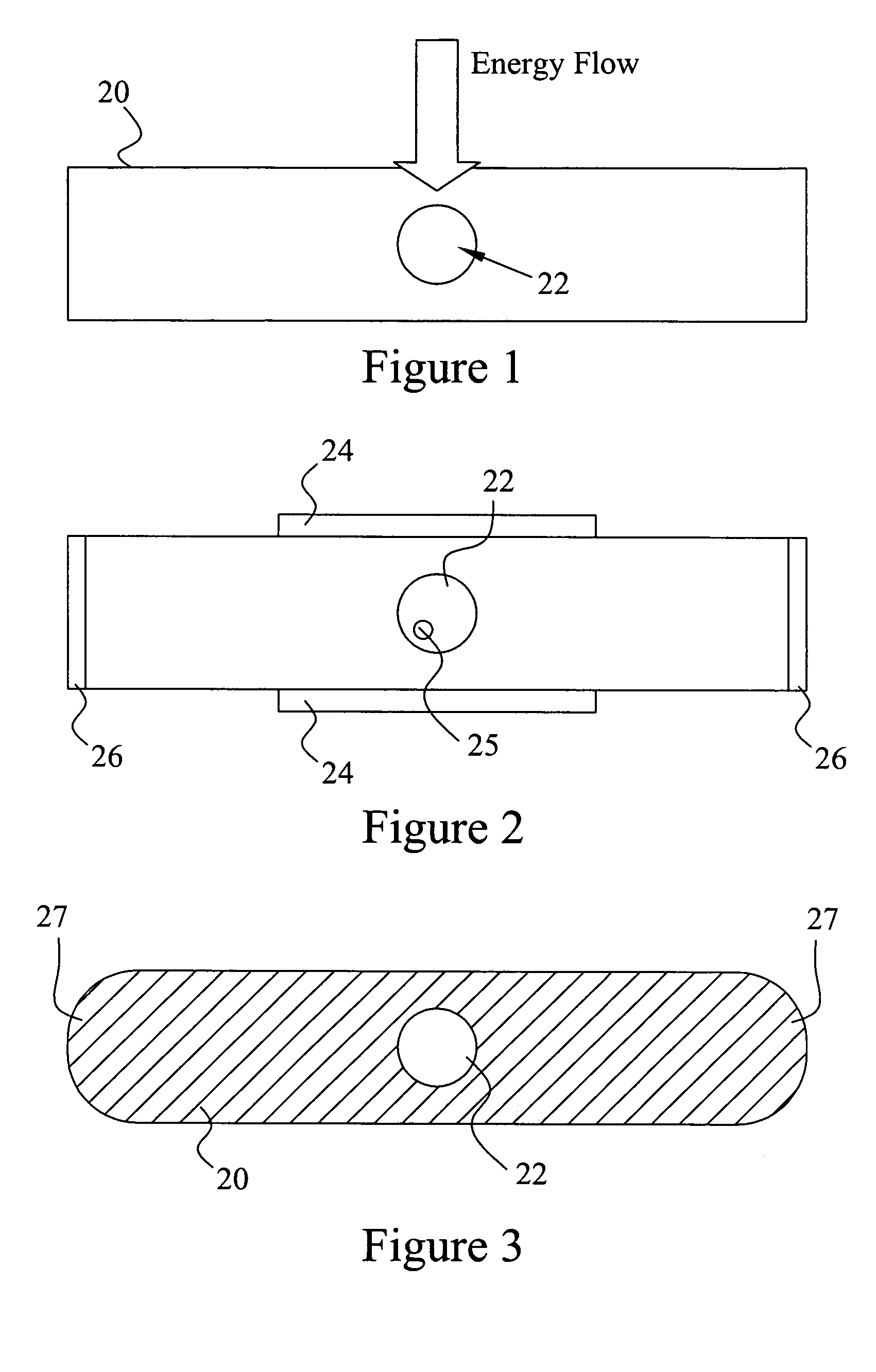
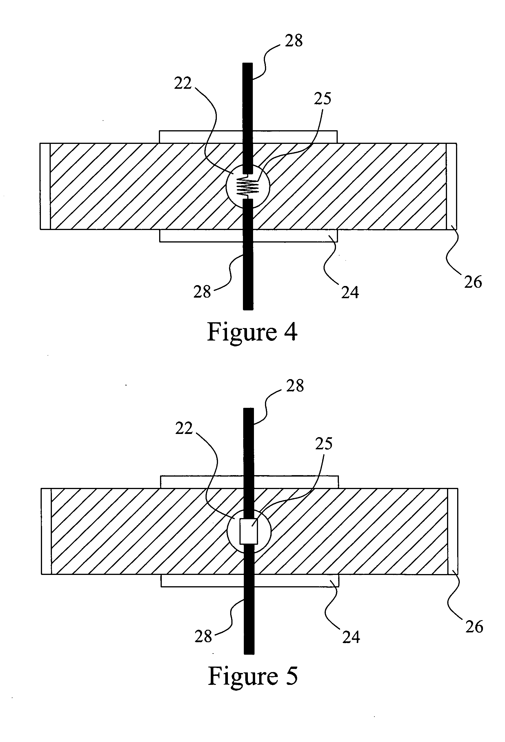
[0026] With reference to the embodiment of FIG. 1, a cylindrical optical waveguide 20 is shown with a cavity 22 positioned on the axis of the waveguide. The waveguide 20 may be made of quartz, ceramics such as Al2O3, transparent plastic or other material through which energy may flow into a source 25 positioned within the cavity 22 and through which light may transmitted. While only the area of the waveguide 20 that is proximate to the cavity 22 is illustrated in FIG. 1, it is to be understood that a further optical waveguide may be carried on both ends of such area as a continuation of the waveguide 20.

[0027] The energy for exciting the source 25 positioned within the cavity 22 may come from any suitable conventional source of electrical power, or from radiation such as RF, microwave, photons for another light source, gamma rays or cosmic rays, depending on the sourced selected. The light source 25 may be any suitable conventional source such as a discharge lamp, electroded or ele...


PUM


Abstract

An optical system and method including an integrated light source and optical waveguide that relies on internal reflection for coupling the light emitted from the source to the waveguide. The light source may include electroded or electrodeless plasma lamps, LEDs, and filament lamps. The optical waveguide may be shaped to form a compound parabolic waveguide. A system may also include an integrated light source, microwave waveguide, and optical coupler.

Description

CLAIM OF PRIORITY [0001] This application claims the filing date priority of U.S. Provisional Patent Application No. 60 / 505,429 filed Sep. 25, 2003, and U.S. Provisional Patent Application No. 60 / 524,612 filed Nov. 25, 2003. The contents of each application is incorporated herein by reference.BACKGROUND OF THE INVENTION [0002] The present invention relates generally to the coupling of electromagnetic waves into an electromagnetic waveguide, and particularly to the coupling of light (visible and / or non-visible) from a source into an optical waveguide. [0003] Distributed lighting systems are well known and include a light source, optical waveguide and a coupler for coupling the light from the source into the waveguide. Examples of optical waveguides include light pipes and optical fibers. In a conventional system, the coupler is a reflector shaped to change the direction of incident light rays, and the complexity thereof has limited the effectiveness of distributed light systems. The ...

Claims


Application Information

Patent Timeline
IPC IPC(8): G02B6/42
CPCG02B6/4298
Inventor GAO, JU
Owner GAO JU
Why Eureka
Try Eureka