
Continuous dissolving device, continuous dissolving method, and gas-dissolved water supply

a technology of continuous dissolution and continuous dissolution, which is applied in the direction of dissolving, machine/engine, and the nature of treatment water, etc., can solve the problems of inability to achieve desirable results, fluctuation of the concentration of gas or chemical in the produced functional water, and considerable tim

Inactive Publication Date: 2005-05-05
KURITA WATER INDUSTRIES LTD
View PDF2 Cites 19 Cited by
  • Summary
  • Abstract
  • Description
  • Claims
  • Application Information

AI Technical Summary

Benefits of technology

The present invention provides an apparatus for continuous dissolution of gas into a liquid, which can produce stable gas concentrations even when the flow rate of the liquid changes. This is achieved by measuring the flow rate of the liquid and controlling the gas supply based on the measurement. The apparatus can be used to produce water containing dissolved gas, and the gas can be hydrogen, oxygen, nitrogen, helium, argon, ozone, ammonia, carbon dioxide, or a mixture of these gases. The invention also provides a mechanism for controlling the flow rate of the liquid and an apparatus for supplying water containing dissolved gas. The technical effects of the invention include stable gas concentration, improved control of gas dissolution, and efficient production of water containing dissolved gas.

Problems solved by technology

When the amount of supply of the main stream liquid changes due to some outside factors or due to saving of water, a problem arises in the practical operation that the concentration of the gas or the chemical in the produced functional water fluctuates.
This causes another problem in the practical operation in that, at the start of the period of time when the functional water is used, it takes a considerable time until the concentration of the dissolved gas reaches the prescribed value and is stabilized at this value after the start of the supply of the specific gas.
However, the desirable results cannot be obtained even when this mechanism is applied to preparation of the functional water.
The reason is that a functional water having an undesired concentration is prepared at least during the period of time lag by the feed back and the hunting phenomenon in the concentration cannot be prevented even when the so-called PID control is conducted.

Method used


Image

  • Continuous dissolving device, continuous dissolving method, and gas-dissolved water supply
  • Continuous dissolving device, continuous dissolving method, and gas-dissolved water supply
  • Continuous dissolving device, continuous dissolving method, and gas-dissolved water supply

Examples


example 1

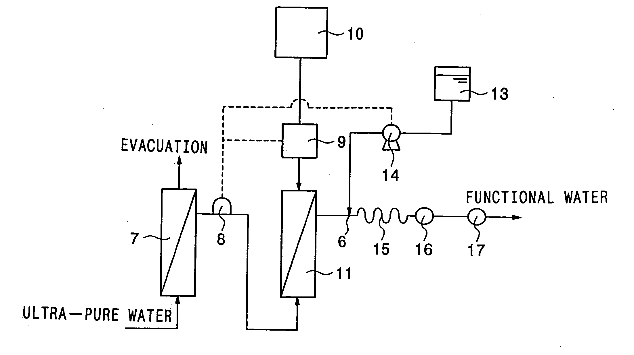
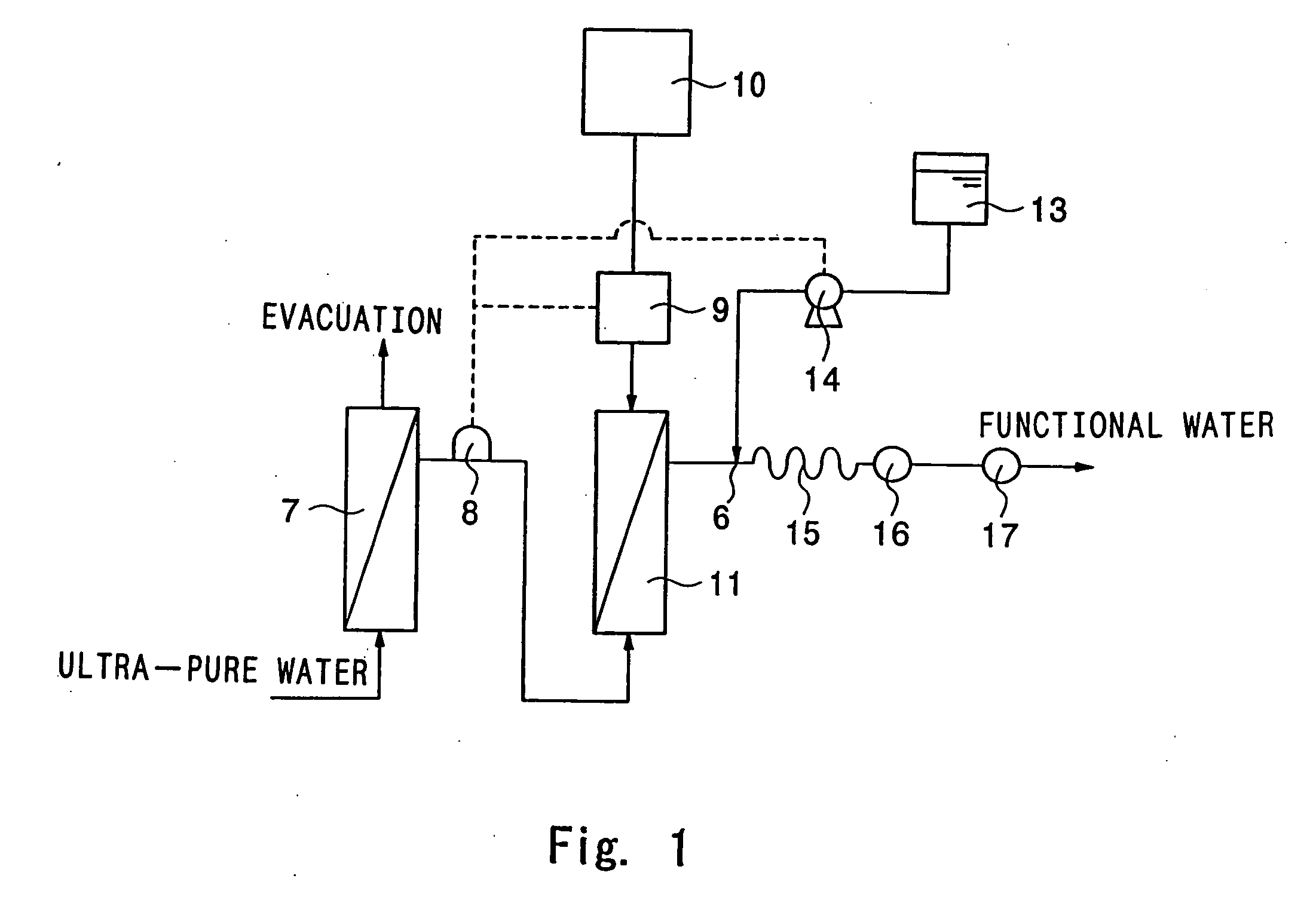
[0057] Hydrogen-dissolved water was produced by using the apparatus for producing a functional cleaning water shown in FIG. 1. The used ultra-pure water contained 10 to 18 ppm of dissolved nitrogen gas and 0.01 to 2 ppm of dissolved oxygen gas. The ultra-pure water was passed through a membrane apparatus for degassing and degassed until the concentration of the dissolved nitrogen gas was 1.5 ppm or smaller and the concentration of the dissolved oxygen gas was 0.5 ppm or smaller. The degassed ultra-pure water was supplied to the dissolution portion. The signal of the flow rate of the ultra-pure water was output from the Karman's vortex flow meter and the amount of supply of hydrogen gas was controlled proportionally to the flow rate of the ultra-pure water by the mass flow controller. Hydrogen was dissolved into the ultra-pure water at the dissolution portion having a module having a built-in gas-permeating membrane and hydrogen-dissolved water was produced.

[0058] The production of ...


PUM

PropertyMeasurementUnit
concentrationaaaaaaaaaa

Abstract

An apparatus for continuous dissolution comprising a dissolution portion for dissolving a gas into a main stream liquid, which comprises a flow meter measuring the flow rate of the main stream liquid and outputting a signal of the value obtained by the measurement and a mechanism for controlling the flow rate which controls the amount of supply of the gas based on the input signal; and a process for continuously dissolving a gas into the main stream liquid, wherein the amount of the gas is controlled based on the flow rate of the main stream liquid. Since a solution having a constant concentration can be obtained with stability even when the flow rate of the main stream liquid changes, cleaning water or surface treatment water used for electronic materials which particularly require a precisely clean surface can be supplied without loss.

Description

TECHNICAL FIELD [0001] The present invention relates to an apparatus for continuous dissolution and a process for continuous dissolution. More particularly, the present invention relates to an apparatus for continuous dissolution and a process for continuous dissolution which can supply, without loss, cleaning water or surface treatment water used for electronic materials which particularly requires a precisely clean surface and to an apparatus for supplying water for cleaning containing a dissolved gas which is equipped with the apparatus for continuous dissolution. BACKGROUND ART [0002] In the wet cleaning process for electronic materials, the so-called functional water for cleaning which is prepared by dissolving a minute amount of a specific gas or a specific chemical into ultra-pure water has been recognized to be useful and is being used more widely. Apparatus using a module having a built-in gas-permeating membrane in the portion for dissolution or in the portion for degassin...

Claims


Application Information

Patent Timeline
Patent Type & Authority Applications(United States)
IPC IPC(8): C02F1/00B01F1/00B01F3/04B01F3/08B01F15/00B01F15/04C02F1/68H01L21/304
CPCB01F3/0446B01F3/04985B01F15/00123B01F15/00136B01F15/00344C02F2103/346B01F15/0479B01F2201/01B01F2215/0036B01F2215/0096B01F15/0412B01F23/232B01F23/29B01F35/2111B01F35/20B01F35/2211B01F35/83B01F35/883B01F2101/2204B01F2101/58B01F23/23764C02F1/68C02F1/78B01F21/00B01F23/40
Inventor MORITA, HIROSHIIDA, JUNICHITSUKAMOTO, KAZUMI
Owner KURITA WATER INDUSTRIES LTD
Learn More