Storage vessel

Active Publication Date: 2005-05-05
H2SAFE
View PDF38 Cites 10 Cited by
  • Summary
  • Abstract
  • Description
  • Claims
  • Application Information

AI Technical Summary

Benefits of technology

[0017] wherein the substance can move from one chamber to another and wherein the configuration of the chambers creates a circuitous path that restricts the rate of flow of the substance through the storage vessel,
[0072] It is anticipated that the controlled release of fuel, even at a high velocity, from the storage vessel of the present invention will minimise the risk of explosion from an impact. It is acknowledged there remains a risk of the released fuel adding to other fuel elements in the environment and helping to sustain a fire. However, release from the storage vessel would not result in an explosion, nor a fireball moving at high speed. Moreover, because the present invention is very unlikely to disintegrate, there is little danger posed to bystanders from exploding shrapnel.

Problems solved by technology

Conventional cylinders typically consist of a single chamber and are designed to be resistant to puncture from minor impacts, but generally are not designed to withstand serious trauma.
However, such baffles typically do not increase the ability of the vessel to withstand serious impacts.
A single chamber design does not exert any control over the release of fuel when such storage vessels are punctured, typically resulting in an explosive release of pressurised fuel from the vessel.
In the presence of a flame or spark, the sudden release of large quantities of fuel may result in a high speed fireball.
Alternatively, a flame could burn back into the vessel, exploding the remaining fuel content and vessel and creating a serious hazard from flying shrapnel.
As such, the complexity of these devices makes them expensive and not suitable for use for small storage situations such as automobiles.
Further, in the event that an automobile is involved in a collision it is possible the storage vessel will be subjected to a violent impact.

Method used


Image

  • Storage vessel
  • Storage vessel
  • Storage vessel

Examples


Embodiment Construction

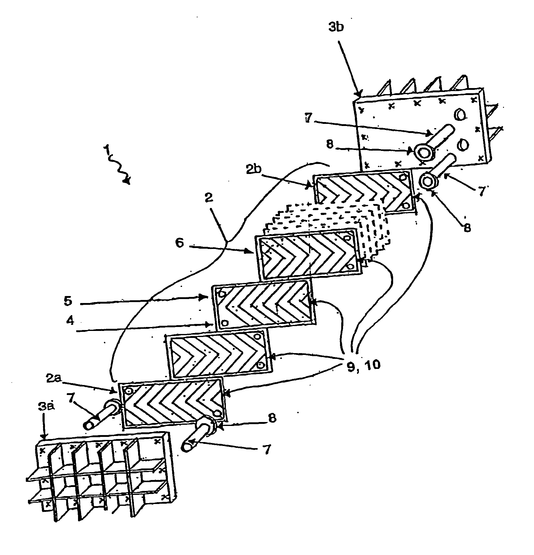
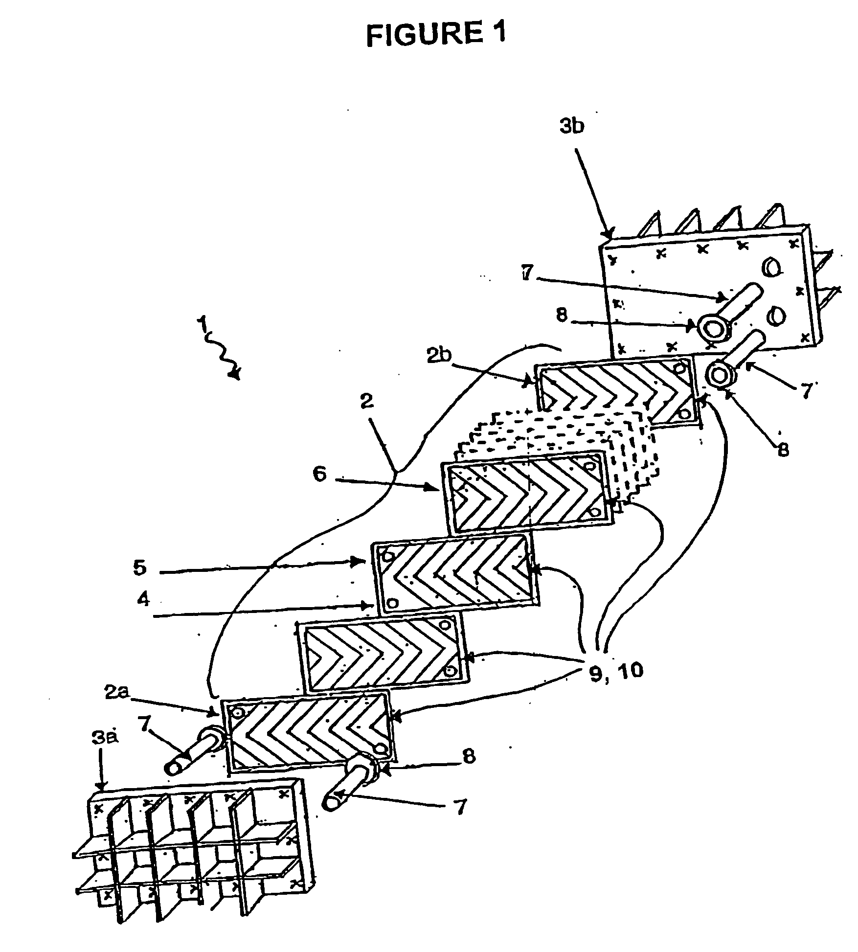
[0077] With reference to the Figures, there is provided a multiple chamber storage vessel (1) for the storage of a fluid substance including liquid or gaseous fuel.

[0078] The vessel (1) consists of a plurality of intermediate panels (2) assembled together, sealed and clamped together between two end panels (3a, 3b).

[0079] Each plate (2) has at least one fuel opening (4) and a vent opening (5). The fuel opening (4) is designed to allow the flow of fuel through the vessel (1). The opening (5) is preferably located at the top to purge any remaining vapour or fuel during filling of the vessel (1).

[0080] The vessel also includes a first panel (2a) and a last panel (2b). These panels (2a, 2b) are of a different configuration to the other panels (2) to facilitate the connection of the vessel (1) to fuel lines of an automobile to allow the filling, emptying and venting of the vessel.

[0081] The panels (2) preferably have a corrugated design, which may be in the form of a chevron or herri...


PUM

PropertyMeasurementUnit
Pressureaaaaaaaaaa
Volumeaaaaaaaaaa
Surfaceaaaaaaaaaa

Abstract

A storage vessel for storing a fluid substance, said storage vessel including a plurality of abutting individually sealed storage chambers, each chamber capable of withstanding super atmospheric pressure, with adjacent chambers forming at least one fluid passageway therebetween, characterised in that at least one said chamber includes an external peripheral seal configured to be relatively weaker than the remainder of said vessel.

Description

CROSS-REFERENCE TO OTHER APPLICATIONS [0001] This Application claims priority from New Zealand Patent Application No. 527968 filed on Sep. 1, 2003. TECHNICAL FIELD [0002] This invention relates to a storage vessel and in particular a vessel for storing a combustible fuel. BACKGROUND ART [0003] A number of storage vessels for combustible fuel are known. [0004] Fuel is commonly stored as a compressed gas or in a liquefied form in a pressurised cylinder. Conventional cylinders typically consist of a single chamber and are designed to be resistant to puncture from minor impacts, but generally are not designed to withstand serious trauma. [0005] When the fuel is in a liquid form, the storage vessel may have a series of baffles to prevent the motion of the liquid from unbalancing the vessel during movement. However, such baffles typically do not increase the ability of the vessel to withstand serious impacts. [0006] A single chamber design does not exert any control over the release of fu...

Claims


Application Information

Patent Timeline
IPC IPC(8): F17C1/00B60K15/00F17C13/12G21C19/00
CPCF17C2209/228F17C2223/035F17C2270/0171F17C2223/0123F17C2203/0663F17C2221/012F17C13/12F17C2201/0171F17C2203/0617Y10T29/49826B60K15/03006F17C2270/0178F17C1/00F17C2221/033F17C2201/0166F17C2209/227F17C2221/035F17C2209/221Y02E60/321F17C2205/035F17C2203/012F17C2203/0636F17C2201/0157F17C2205/0323F17C2260/042F17C2203/0648F17C2270/0176F17C2205/0352F17C2201/056F17C2205/0394F17C2223/0161F17C2203/0643Y02E60/32F17C13/00
Inventor GOGGIN, BRIAN ANTHONY
Owner H2SAFE
Why Eureka
Try Eureka