Stepping motor direct drive adjustable pedal assembly

Inactive Publication Date: 2005-05-05
DRIVESOL WORLDWIDE
View PDF31 Cites 0 Cited by
  • Summary
  • Abstract
  • Description
  • Claims
  • Application Information

AI Technical Summary

Benefits of technology

[0008] Accordingly, the subject invention provides controller used in a multiple pedal assembly whereby the adjustable movement of the respective pedal levers is synchronized by shutting down electrical energy to both pedal levers adjustment motors in the event one of the moto

Problems solved by technology

In order to stay within cost limitations, these assemblies require a relatively large number of parts, are noisy and imprecise in output.
They also present difficult packaging parameters.

Method used


Image

  • Stepping motor direct drive adjustable pedal assembly
  • Stepping motor direct drive adjustable pedal assembly
  • Stepping motor direct drive adjustable pedal assembly

Examples


Embodiment Construction

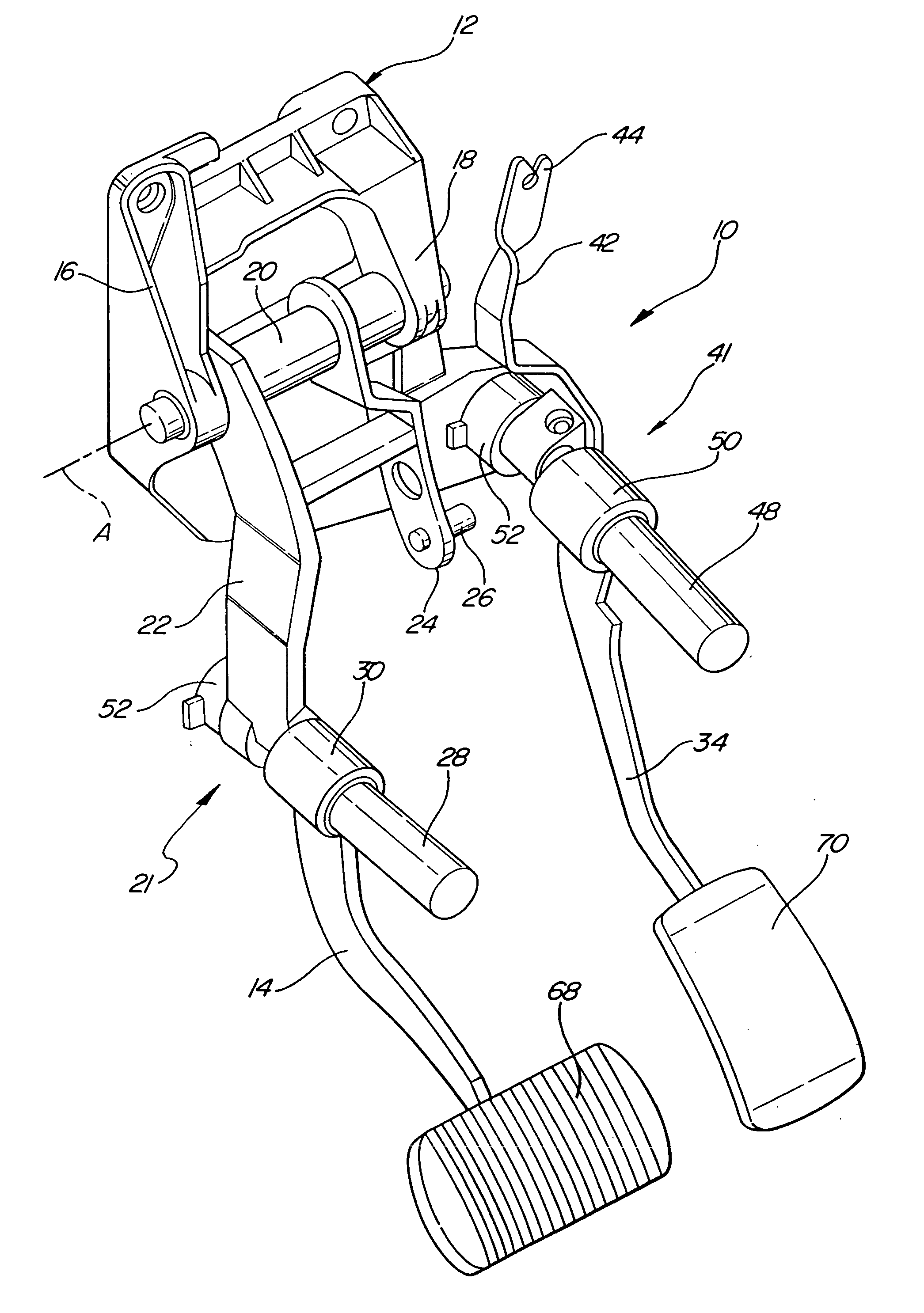
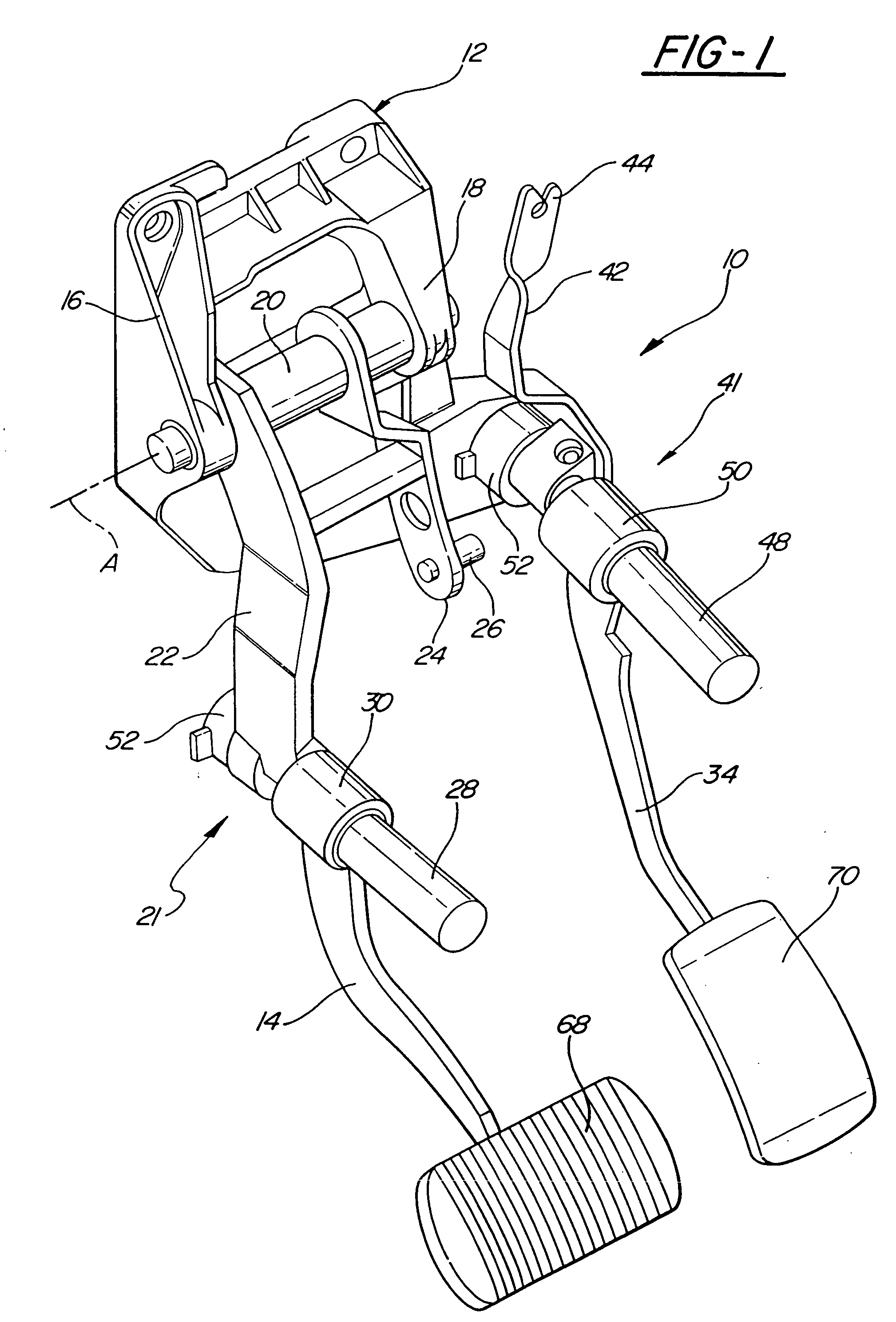
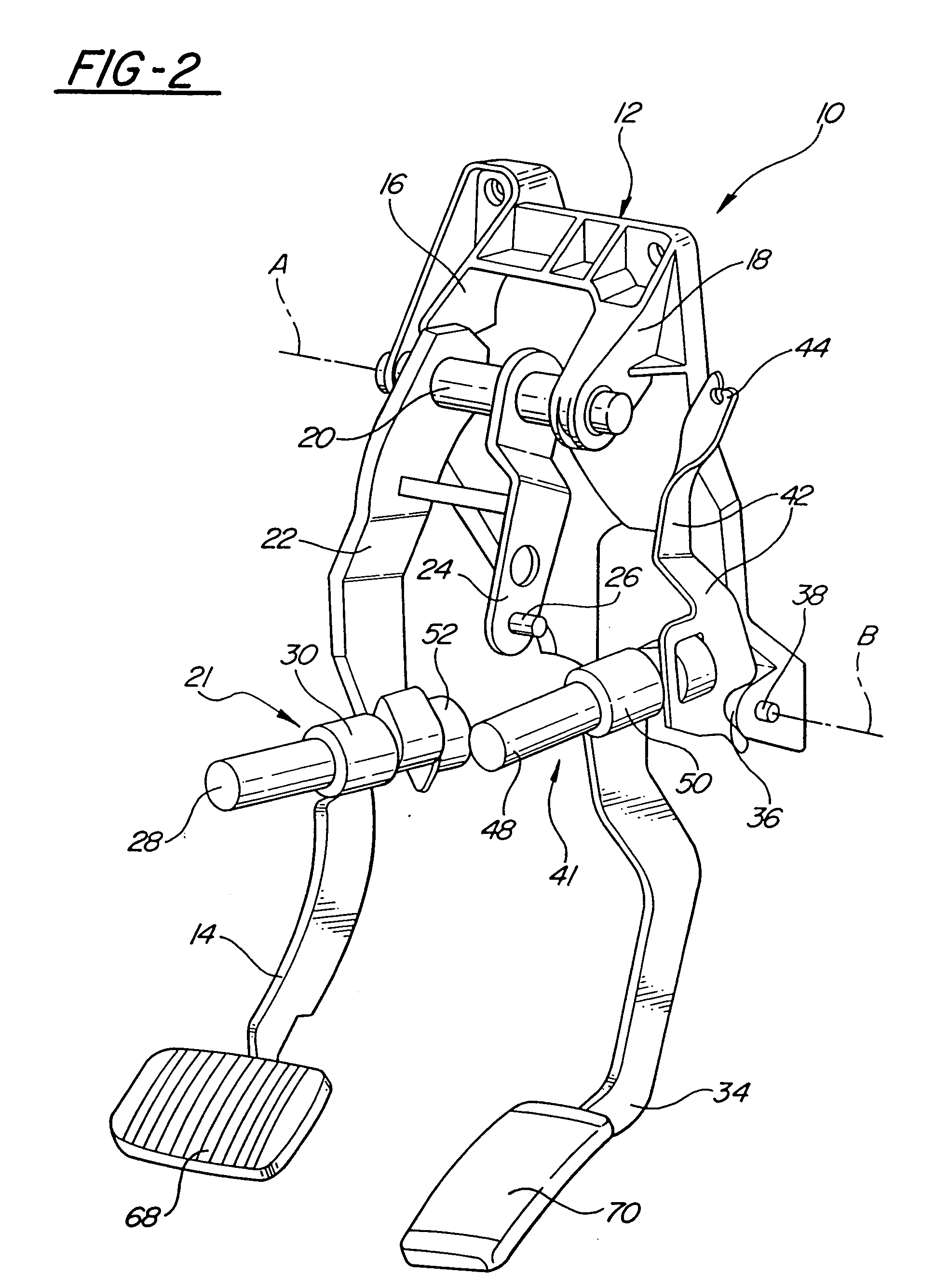
[0020] Referring to the Figures, wherein like numerals indicate like or corresponding parts throughout the several views, an adjustable pedal assembly is generally shown at 10 in FIGS. 1 and 2. A support, generally indicated at 12, is included for mounting the assembly to a vehicle structure.

[0021] A first pedal lever 14 is pivotally supported for rotation about an operational axis A with respect to the support 12. The support 12 comprises a bracket having side flanges 16 and 18 that rotatably support a shaft 20. A first adjustment mechanism, generally indicated at 21, interconnects the support 12 and the pedal lever 14 for adjusting the operational position of the pedal lever 14 relative to the operational axis (A) between a plurality of adjusted positions. More specifically, the shaft 20 supports a first arm 22. A link 24 depends from the shaft 20 and supports an attachment 26 that connects to the vehicle system for operating a system thereof, e.g., a brake system. As is well kno...


PUM


Abstract

A pair of first (14) and second (34) pedal levers is pivotally supported for rotation by a support (12). A pair of adjustment mechanisms (21, 41) interconnect the support (12) and the respective pedal levers (14, 34) and include rods (28, 48) for adjusting the operational position of the pedal levers (14, 34) along the rods (28, 48) between a plurality of adjusted positions. A stepper motor (52) and screw (32) unit is attached to the inner end of each rod (28, 48) for moving the respective pedal levers (14, 34) along the respective rods (28, 48). The assembly (10) is characterized by a controller (56) sending pulses of energy to each of the motors (52), measuring the time to reach a predetermined resistance condition of each motor during each pulse, and terminating energy to both motors (52) in response to the time being below a predetermined time period in any pulse to either motor, thereby to synchronize the movement of both pedal levers together.

Description

RELATED APPLICATION [0001] This application is a continuation-in-part of co-pending application Ser. No. 10 / 040,096 filed Jan. 1, 2002.BACKGROUND OF THE INVENTION [0002] 1. Field of the Invention [0003] The subject invention relates to an adjustable pedal assembly used in an automotive vehicle to vary the operating position of one or more of the foot pedals to mechanically or electrically control various vehicle systems, such as the clutch, brake and throttle systems. [0004] 2. Description of the Prior Art [0005] Typically, adjustable pedal assemblies have used direct current electrical motors to rotate a drive cable that, in turn, rotates a worm gear to adjust the position of the pedal. Examples of such assemblies are shown in U.S. Pat. Nos. 5,632,183; 5,697,260; 5,722,302 and 5,964,125 to Rixon et al, U.S. Pat. No. 3,643,524 to Herring, U.S. Pat. No. 4,875,385 to Sitrin, U.S. Pat. No. 4,989,474 to Cicotte et al and U.S. Pat. No. 5,927,154 to Elton et al. Other assemblies eliminate...

Claims


Application Information

Patent Timeline
IPC IPC(8): G05G1/38G05G1/40
CPCG05G1/405Y10T74/20528Y10T74/20888
Inventor RIXON, CHRISTOPHEROUYANG, JIYUAN
Owner DRIVESOL WORLDWIDE
Why Eureka
Try Eureka