Apparatus and methods for simultaneous operation of miniaturized reactors
- Summary
- Abstract
- Description
- Claims
- Application Information
AI Technical Summary
Benefits of technology
Problems solved by technology
Method used
Image
Examples
example 1
Fabrication of a Microscale Bioreactor
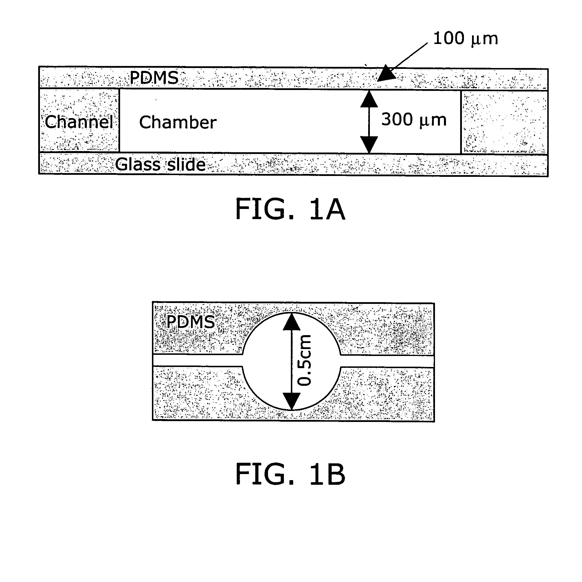
[0241] Poly(dimethylsiloxane) (PDMS) was selected as the microfermentor fabrication material in part because of its biocompatibility and optical transparency in the visible range. The high gas permeability of this material also allows it to be used as the material for an aeration membrane. Glass was selected as the microfermentor base for its transparency and rigidity.
[0242] The fabrication procedure used is depicted in FIG. 10. Fabrication of the microfermentor was carried out using soft lithography as described in (58). In the first step of the fabrication process photolithography was used to fabricate a negative master out of silicon and the photo-definable epoxy SU-8. The body of the microfermentor was then cast in PDMS by squeezing the liquid polymer between the negative master and a piece of cured and passivated (silanized) PDMS. The aeration membrane was made by spin-coating the liquid polymer onto a blank wafer. The body and the membra...
example 2
Modeling Aeration Within a Microscale Bioreactor
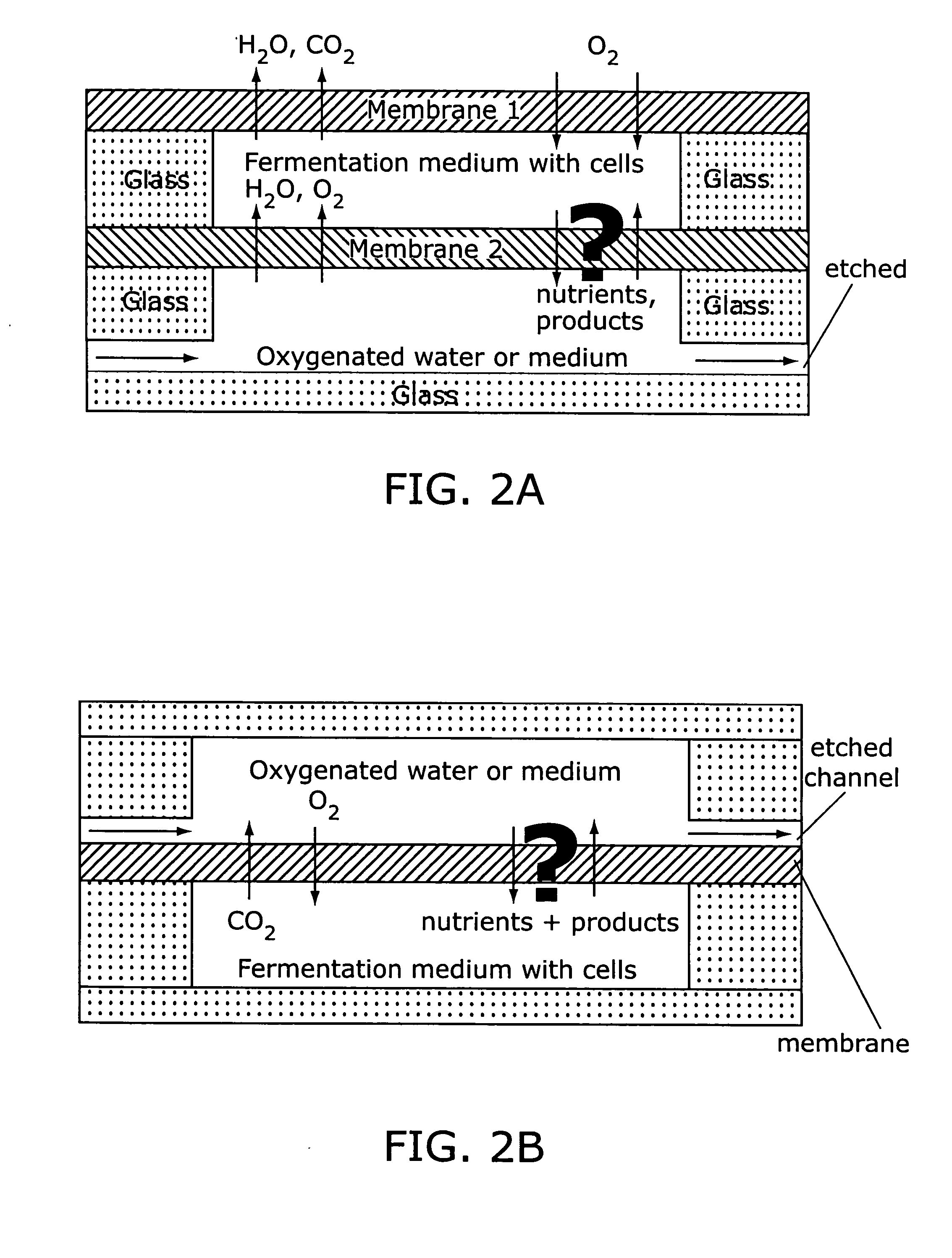
[0243] Modeling of oxygen diffusion into the microfermentor was carried out using a one-dimensional resistance-in-series model of the membrane and the medium, taking oxygen consumption to be a zeroth-order reaction term (constant oxygen consumption / viable cell). For calculations at 35° C., an oxygen diffusivity in PDMS of 3.4×10⁻⁵ cm2 / s and a solubility of 0.18 cm3 (STP) / cm3 / atm were assumed (44). For oxygen in water a diffusivity of 2.5×10⁻⁵ cm2 / s and a solubility of 7 mg / l were used (45), and it is assumed that values for culture medium would be approximately the same. A typical E. coli oxygen uptake rate (OUR) of 30 (mmol O2) / (gram dry cell weight / h) was assumed (46).
[0244] The models assumed a stagnant medium (no mixing). If some method of mixing is implemented, the maximum depth of the microfermentor will increase. The model assumes steady state conditions (see below for transient analysis of oxygen transport during growth). For...
example 3
Setup of a Microscale Bioreactor System
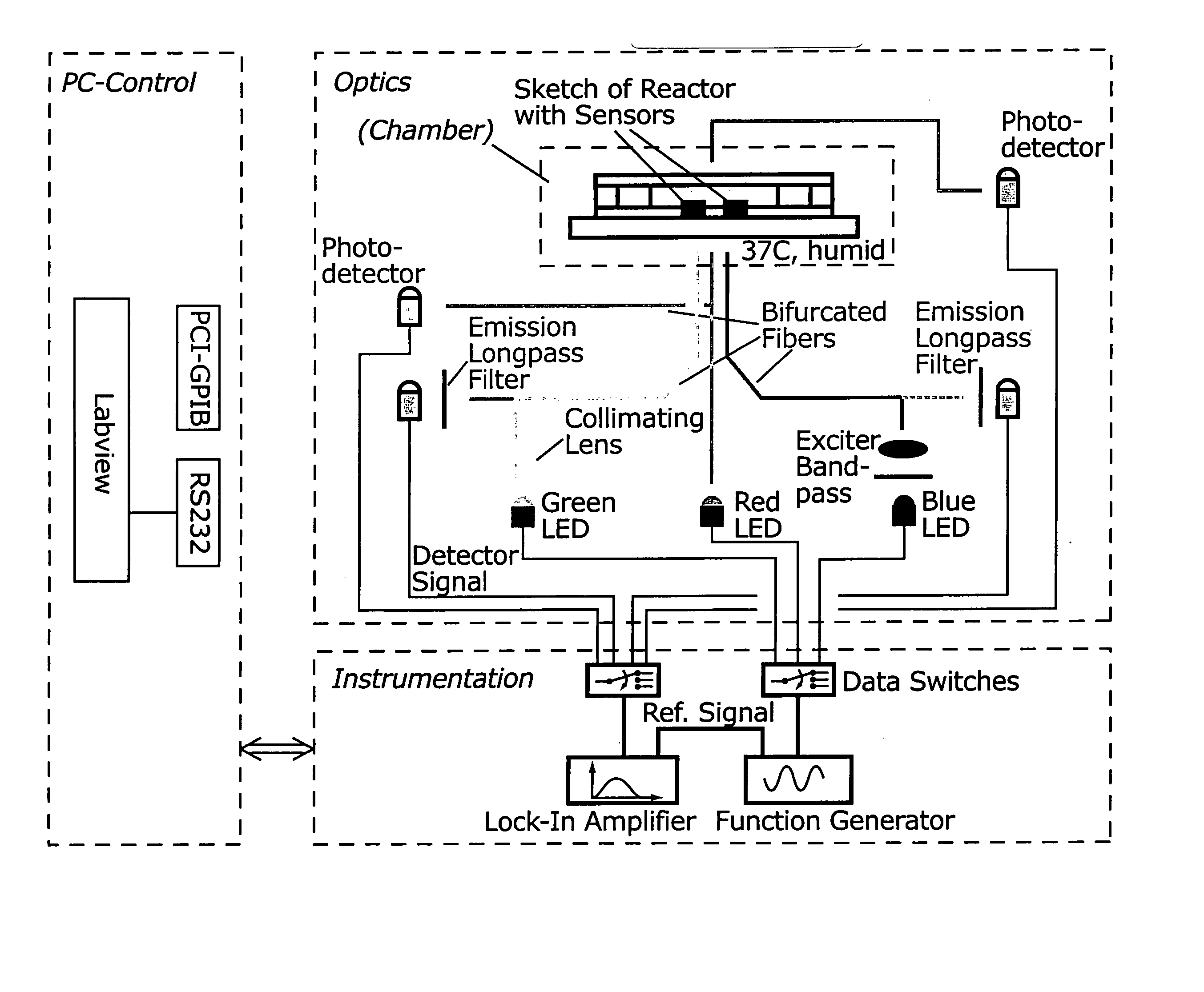
[0262]FIG. 14 shows a schematic of a microscale bioreactor system with associated optical excitation and detection sources. Optical fibers transmit light to the bottom of the fermentor. Biomass is monitored by measuring the amount of light transmitted to the collecting lens above.
[0263] The microfermentor is placed in an enclosed chamber designed to facilitate environmental control during fermentations. The chamber is fabricated from aluminum and has a screw-on lid that can be sealed with an O-ring. FIG. 15A depicts the chamber with the microfermentor inside. FIG. 15B is a second view to more clearly show the microfermentor. (Note that the slide that forms the base of the microfermentor is transparent.) In this system, evaporation from the microfermentor is controlled by making the chamber airtight and by maintaining the air within the chamber at high humidity, e.g., 100% humidity. This is accomplished by placing open reservoirs of water besi...
PUM
 Abstract
Description
Claims
Application Information
 - R&D
- Intellectual Property
- Life Sciences
- Materials
- Tech Scout
- Unparalleled Data Quality
- Higher Quality Content
- 60% Fewer Hallucinations
Browse by: Latest US Patents, China's latest patents, Technical Efficacy Thesaurus, Application Domain, Technology Topic, Popular Technical Reports.
© 2025 PatSnap. All rights reserved.Legal|Privacy policy|Modern Slavery Act Transparency Statement|Sitemap|About US| Contact US: help@patsnap.com


