Francis turbine

a turbine and turbine blade technology, applied in the field of turbine blades, can solve problems such as loss of hydraulic efficiency, and achieve the effects of reducing a circumferential velocity component, improving the shape of blades, and reducing secondary flow

Inactive Publication Date: 2005-04-28
KK TOSHIBA
View PDF7 Cites 8 Cited by
  • Summary
  • Abstract
  • Description
  • Claims
  • Application Information

AI Technical Summary

Benefits of technology

[0010] Accordingly, an advantage of an aspect of the present invention is to provide a Francis turbine with an improved shape of blades that can reduce a circumferential velocity component generated in the flow downstream of the blades in a condition of a partial load operation, or reduce the secondary flow around the blades.

Problems solved by technology

Especially, it is known that secondary flow, which is a flow not being along a flow line, distorts a pressure distribution on the blades and results in loss of hydraulic efficiency.

Method used


Image

  • Francis turbine
  • Francis turbine
  • Francis turbine

Examples


first embodiment

[0020] A first embodiment in accordance with the present invention will be explained with reference to FIGS. 1 to 3.

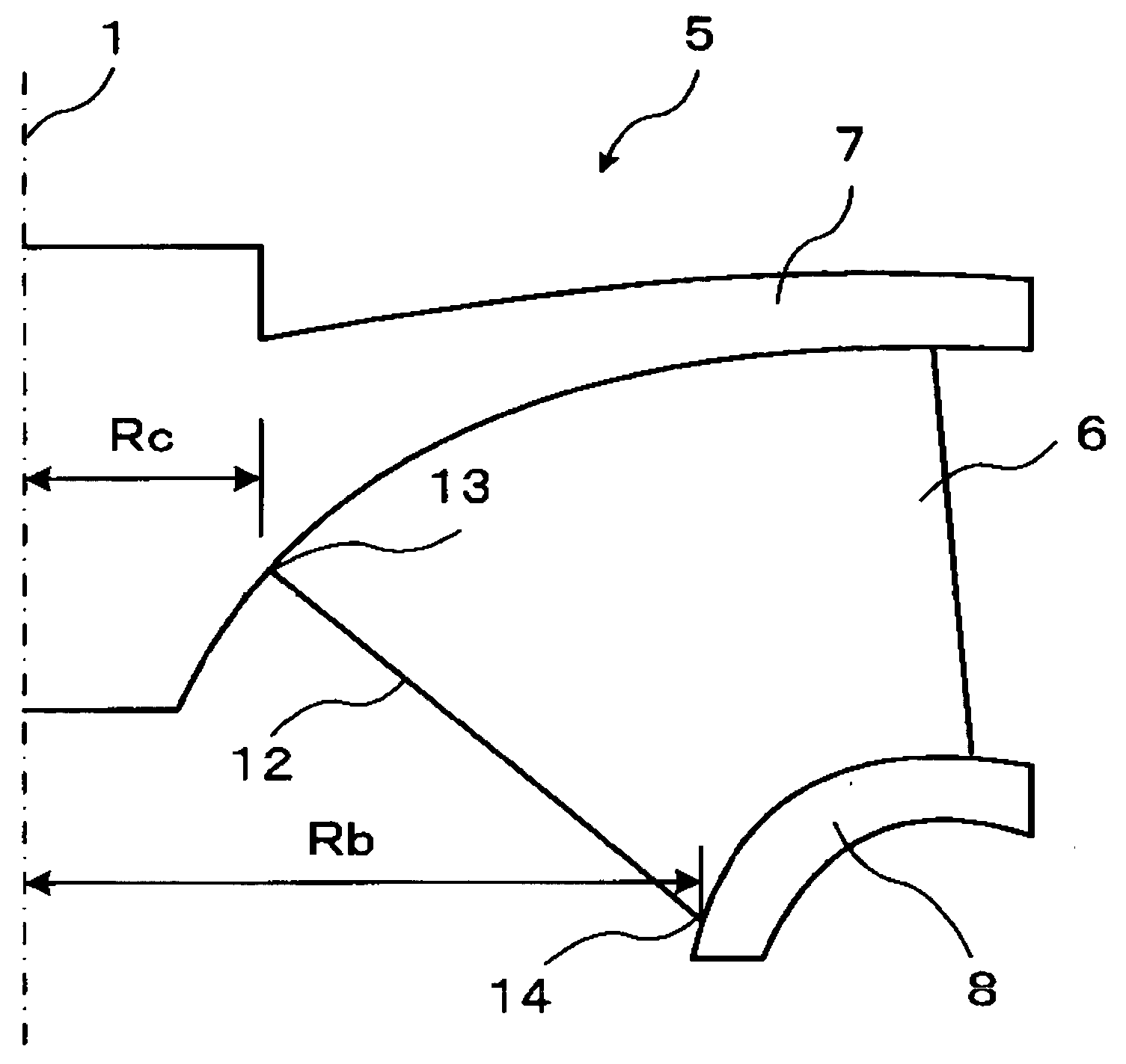
[0021]FIG. 1 is a half cross sectional view including a center axis of a Francis turbine runner according to the first embodiment. Since the Francis turbine runner rotates around the center axis (also referred to as a rotation axis), half of the drawing is omitted as it has a symmetric profile in FIG. 1.

[0022] As shown in FIG. 1, a Francis turbine runner 5 includes a crown 7, a band 8, and a plurality of runner blades 6. Crown 7 is connected to a rotating shaft (not shown) at a rotation axis 1. Runner blades 6 are circumferentially arranged on the crown 7. In FIG. 1, one of runner blades 6 is shown as a projected profile on a meridian plane, which is a plane including the rotation axis 1. Band 8 is connected to runner blades 6 and is arranged so that the rotation axis 1 becomes in the center. Thus, band 8 is coaxially coupled with the crown 7 by the runner blades 6. I...

second embodiment

[0035] A second embodiment in accordance with the present invention will be explained with reference to FIGS. 4 to 6.

[0036]FIG. 4 is a half cross sectional view including a center axis of a Francis turbine runner according to the second embodiment. Since the Francis turbine runner rotates around the center axis (also referred to as a rotation axis), half of the drawing is omitted as it has a symmetric profile in FIG. 4. The same symbols are used for the same elements shown in FIG. 1 and detailed description of those elements is omitted.

[0037] As shown in FIG. 4, a Francis turbine runner 5 includes a crown 7, a band 8, and a plurality of runner blades 6. Crown 7 is connected to a rotating shaft (not shown) at a rotation axis 1. Runner blades 6 are circumferentially arranged on the crown 7. Band 8 is connected to runner blades 6 and is arranged so that the rotation axis 1 becomes in the center. Thus, band 8 is coaxially coupled with the crown 7 by the runner blades 6. Same as FIG. 1,...


PUM


Abstract

A Francis turbine with an improved shape of blades, which can reduce a circumferential velocity component generated in the flow downstream of the blades in a condition of a partial load operation, or reduce the secondary flow around the blades, is provided. A Francis turbine comprises a crown, a plurality of blades, and a band. The crown can rotate around a rotating axis. The blades are circumferentially arranged on the crown, each of which including an inner end as a trailing edge. The band is coaxially coupled with the crown by the blades. A distance Rc can be defined as a distance between the rotation axis and an end by the crown side of the trailing edge. A distance Rb can be defined as a distance between the rotation axis and an end by the band side of the trailing edge. The distance Rc and the distance Rb satisfy 0.2RcRb0.4.

Description

CROSS REFERENCE TO RELATED APPLICATION [0001] This application is based upon and claims the benefit of priority from prior Japanese Patent Application No. 2003-291266 filed on Aug. 11, 2003, the entire contents of which are incorporated herein by reference. FIELD OF THE INVENTION [0002] This invention relates to a Francis turbine that is used for a hydraulic turbine or a pump, and in particular, a Francis turbine having blades with an improved shape on a trailing edge. BACKGROUND [0003] A Francis turbine is used in a hydraulic machine, including a reversible pump-turbine, for power generation. [0004] A conventional Francis turbine runner is described in U.S. Pat. No. 4,479,757. This conventional Francis turbine runner includes blades whose inlet (a leading edge) shape is curved toward a direction opposite to a rotating direction of a turbine operation from a band side to a crown side. [0005] Another conventional Francis turbine runner is described in U.S. Pat. No. 6,135,716. This co...

Claims


Application Information

Patent Timeline
Patent Type & Authority Applications(United States)
IPC IPC(8): F03B3/12F01D17/12F03B3/02F03B3/10
CPCF03B3/125Y10S416/02Y02E10/223Y02E10/20
Inventor ENOMOTO, YASUYUKISUZUKI, TOSHIAKIKUROSAWA, SADAONAKAMURA, TAKANORI
Owner KK TOSHIBA
Why Eureka
Try Eureka