
Dynamizable orthopedic implants and their use in treating bone defects

Inactive Publication Date: 2005-04-21
SDGI HLDG
View PDF57 Cites 231 Cited by
  • Summary
  • Abstract
  • Description
  • Claims
  • Application Information

AI Technical Summary

Benefits of technology

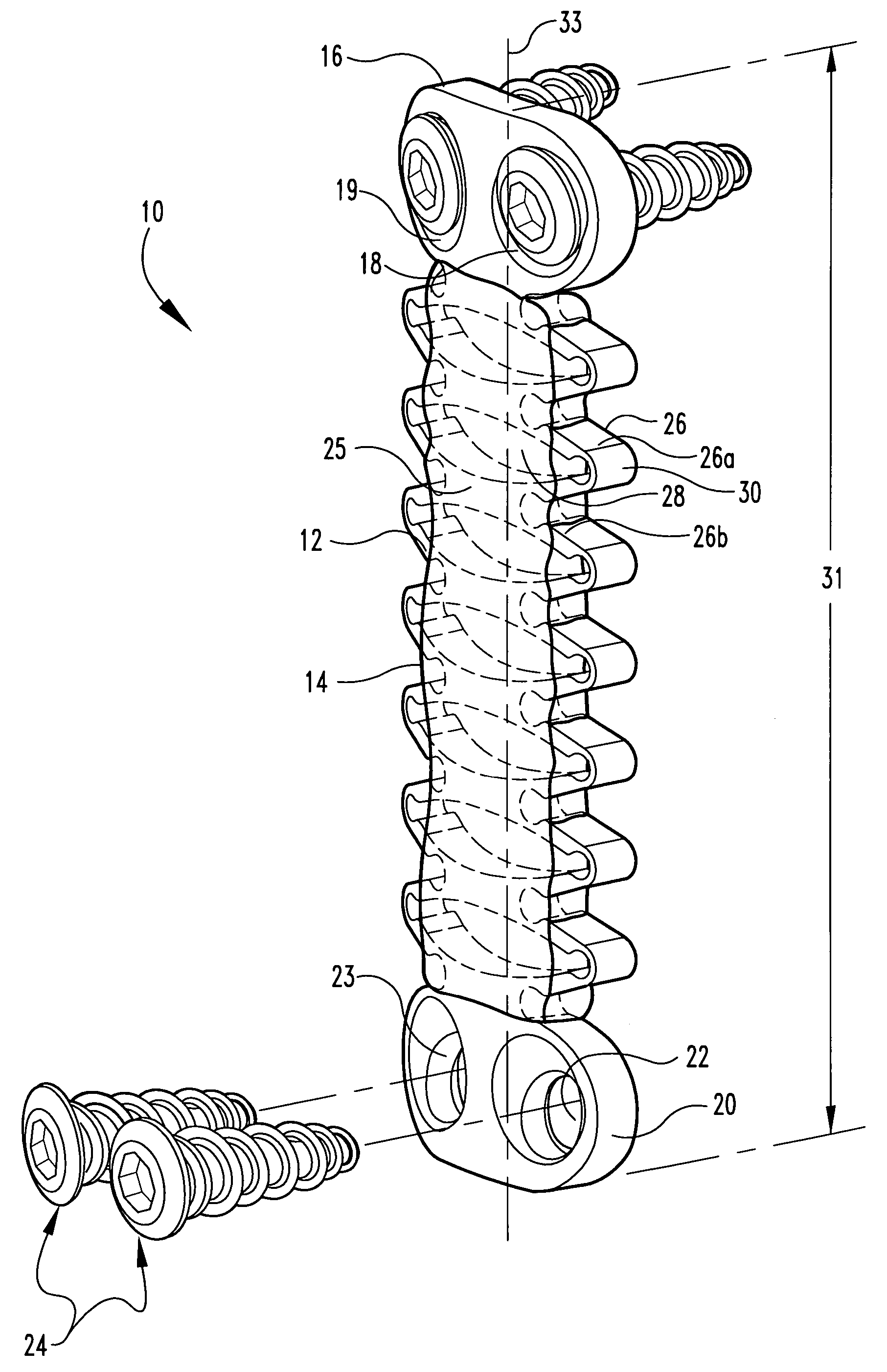
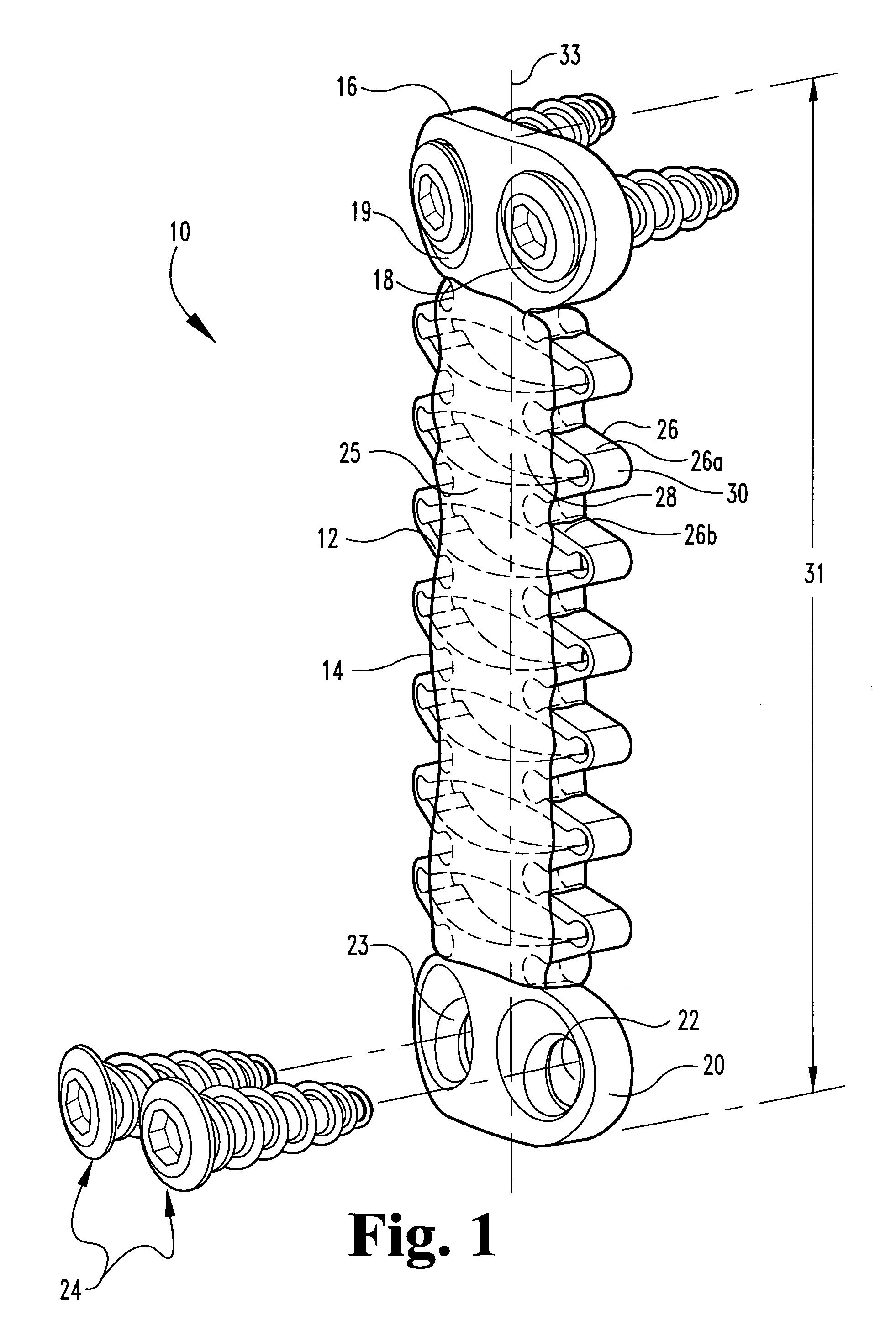
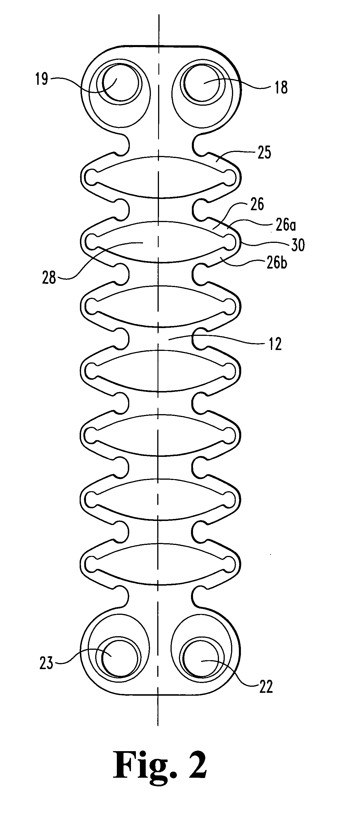
[0010] In another form, the present invention provides a method for treating a bone defect. The method comprises providing an orthopedic device including an elongate member configured to be deformable in vivo, and a reinforcing component encasing at least a portion of the elongate member. The reinforcing component comprises a biodegradable material, which is formulated to inhibit deformation of the elongate member. The first end of the elongate member can be secured to first bony structure and the second end of the elongate structure can be secured to a second bony structure. The secured device can support and effectively immobilize the two bone portions relative to each other. In vivo, the reinforcing component can be degraded and be eliminated either in whole or in part from the device. This effectively transfers at least a portion of the biomechanical load and support to the treated site, in general, and to new tissue and bone growth, in particular. Further particularly for articulating joints and if desired, the treated site can then be allowed at least a limited amount of movement, i.e. translation and / or rotation. The secured devices without the reinforcing component can be allowed to remain in place indefinitely.

Problems solved by technology

Unfortunately, the spine, like any complex physiological structure, is also vulnerable to disease, injury, and congenital deficiencies, all of which can cause defects to the spine and, in particular, to the vertebral body and intervertebral discs.
Spinal disease, injury, and deformity may have a disastrous impact on patient well being, ranging from acute pain to chronic debilitating pain, and, in the most severe cases, partial or complete paralysis.
The problem arises when and how to determine the amount of pressure or force desirable to develop a strong junction between the bone portions.
Further, the treated ligaments can be susceptible to repeated injury.
Current treatment methods do not allow for an implanted device to initially secure / immobilize the ligaments and then allow limited movement of the same without a subsequent surgical revisitation.

Method used


Image

  • Dynamizable orthopedic implants and their use in treating bone defects
  • Dynamizable orthopedic implants and their use in treating bone defects
  • Dynamizable orthopedic implants and their use in treating bone defects

Examples


Embodiment Construction

[0024] For the purposes of promoting an understanding of the principles of the invention, reference will now be made to the embodiments illustrated herein and specific language will be used to describe the same. It will nevertheless be understood that no limitation of the scope of the invention is thereby intended. Any alterations and further modifications in the described devices, systems, and treatment methods, and any further applications of the principles of the invention as described herein, are contemplated as would normally occur to one skilled in the art to which the invention relates.

[0025] In preferred embodiments, the present invention provides an implantable orthopedic device or prosthesis to facilitate support and repair of defective bone structures and / or connective tissue. The defective bone structures can be the result of damaged, traumatized, and / or diseased tissue. By use of the term orthopedic device, it is intending to include within its meaning a device that ca...


PUM


Abstract

The present invention generally relates to bone fixation devices and methods for promoting arthrodesis of bone defects. The bone fixation devices can provide sufficient support to the bone defect while allowing bone ingrowth and minimizing the risk to stress shield and / or pseudo-arthrodesis. The bone fixation devices include a degradable component that allows the device to gradually transfer the load from the supporting member to the growing bone structure in vivo.

Description

BACKGROUND OF THE INVENTION [0001] The present invention relates generally to orthopedic devices for promoting bone fusion and methods for treating orthopedic defects using the orthopedic devices. [0002] The spine is composed of both rigid and flexible elements, forming a complex structure that can readily accommodate a wide range of motions and adjust to a wide range of loads. Unfortunately, the spine, like any complex physiological structure, is also vulnerable to disease, injury, and congenital deficiencies, all of which can cause defects to the spine and, in particular, to the vertebral body and intervertebral discs. Spinal disease, injury, and deformity may have a disastrous impact on patient well being, ranging from acute pain to chronic debilitating pain, and, in the most severe cases, partial or complete paralysis. [0003] Some of the most common pathologies of spinal defects include fractured, diseased, or decayed vertebral bodies, torn or stretched ligaments, and damaged or...

Claims


Application Information

Patent Timeline
IPC IPC(8): A61B17/00A61B17/70A61B17/80
CPCA61B17/7004A61B17/7026A61B2017/00004A61B17/8004A61B17/8085A61B17/7059
Inventor SHERMAN, MICHAEL C.JUSTIS, JEFF R.
Owner SDGI HLDG
Learn More