
Exercise resistance

a technology of resistance and weight, applied in the field of exercise equipment, can solve the problems of difficult to achieve with conventional weight training equipment such as a bench press machine or other general purpose, unnecessarily interrupting exercise, and difficult or impossible to reach afp, etc., and achieve the effect of facilitating the change of weight resistan

Inactive Publication Date: 2005-04-21
EXERTRON LLC
View PDF9 Cites 49 Cited by
  • Summary
  • Abstract
  • Description
  • Claims
  • Application Information

AI Technical Summary

Benefits of technology

[0008] Among the various objects and features of the present invention may be noted that the provision of a resistance system for an exercise machine which facilitates the changing of weight resistance in response to conditions such as MMF.
[0010] A third object of the present invention is the provision of such a system which is economical and reliable.

Problems solved by technology

This is difficult to achieve with conventional weight training equipment such as a bench press machine or other general purpose or special purpose machines since generally the athlete has heretofore stopped exercising when he reaches his first point of momentary muscular failure (MMF).
This either unnecessarily interrupts the exercise, or requires the continual presence of a second, non-exercising partner.
However, with conventional exercise equipment, the AFP is extremely difficult or impossible to reach due to the drawbacks described above.
Soon, for example after only ten complete repetitions, this athlete is no longer able to complete another repetition.
However, it has been discovered that conventional weight stacks are not optimally suited to systems that automatically change the weight resistance upon occurrence of conditions such as MMF.
Changing the weight resistance automatically in such a system can be complicated and expensive.
The first alternative is costly and complicated, while the second is merely complicated.

Method used


Image

  • Exercise resistance
  • Exercise resistance
  • Exercise resistance

Examples


Embodiment Construction

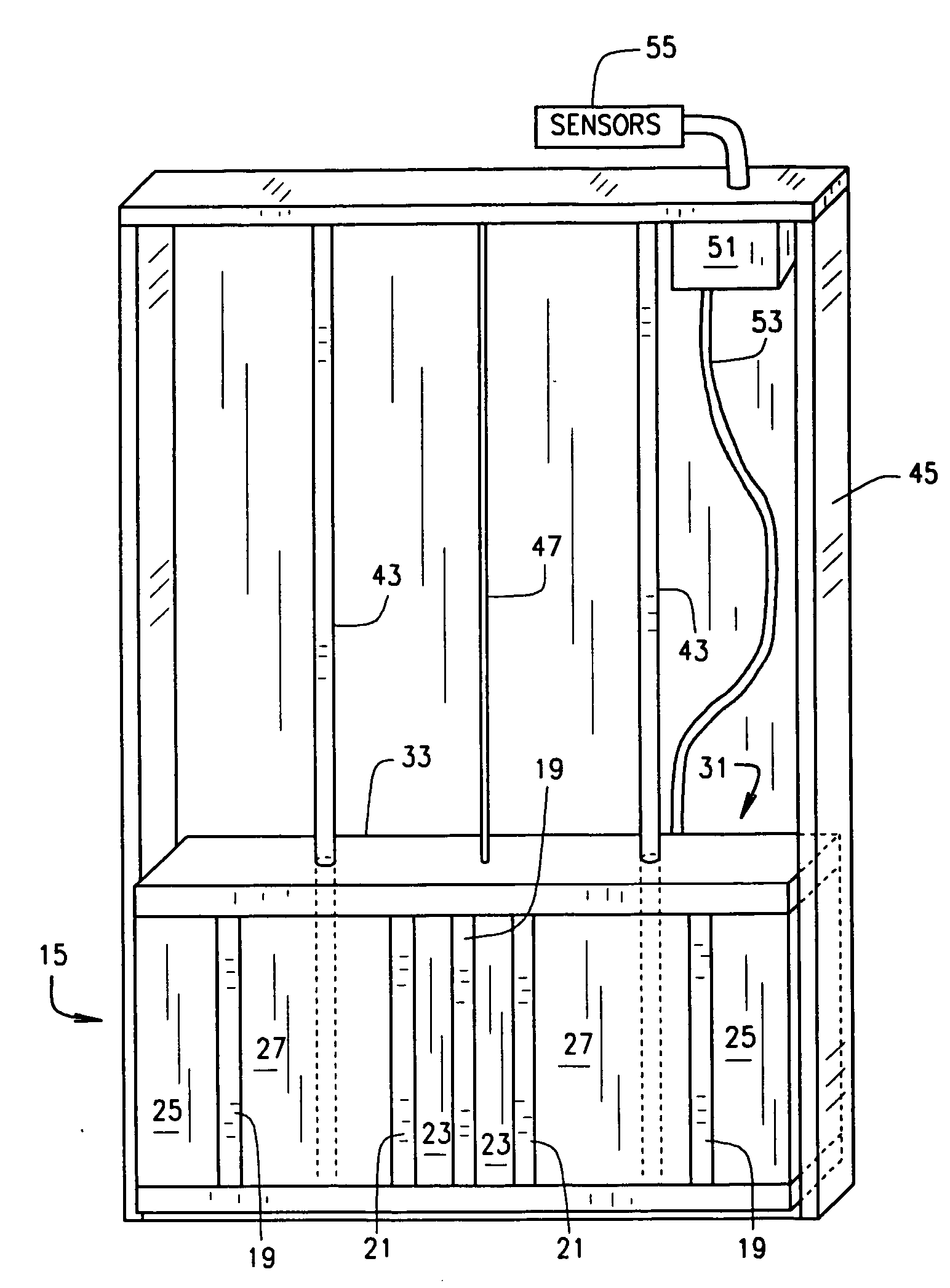
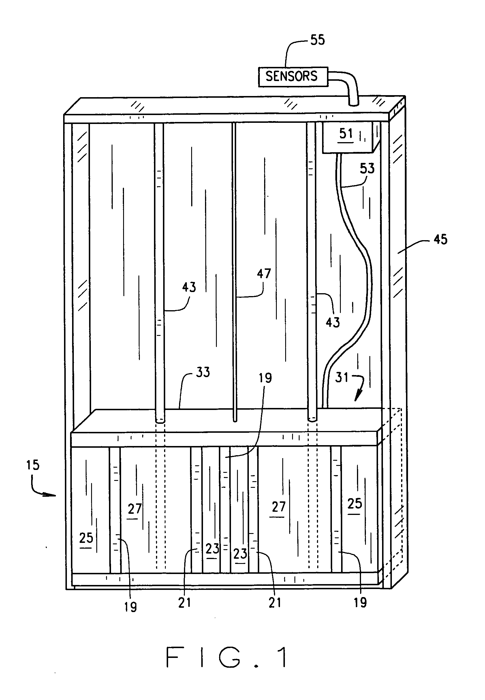
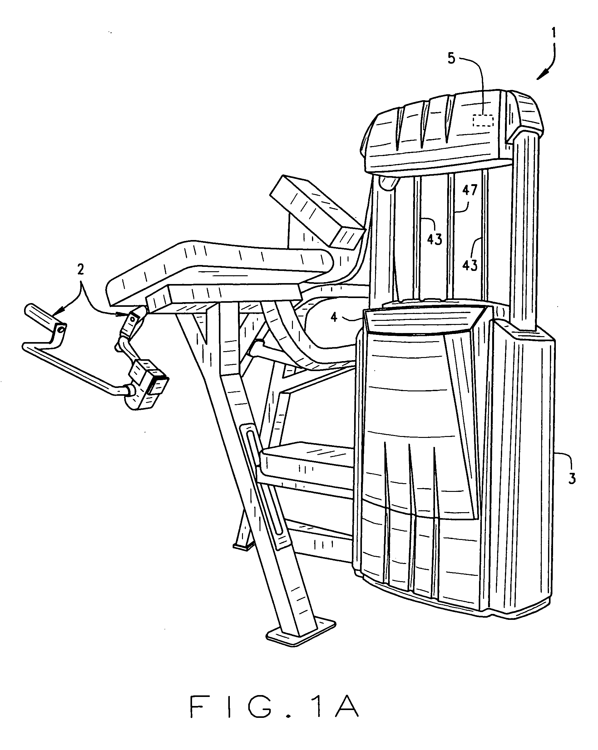
[0027] Turning to FIG. 1, a resistance system 11 of the present invention is designed for use in connection with any conventional exercise machine 13 (only a portion of the conventional exercise machine is shown). It should be understood that the present invention is not limited to any particular type of exercise machine, but rather is applicable to all and is intended to be so used. For example, FIG. 1A shows a conventional exercise machine 1 having a manually operable members 2 that the user using to exercise against resistance. The particular machine 1 shown has a cowling 3 with a readout 4 covering the weight stack (described below). Preferably, a sensor 5 is disposed either in the lower or upper portion of the cowling on the exercise machine to sense the condition (speed, force, etc.) of the exercise to determine when a change is resistance would be beneficial. Although an exercise machine in the conventional sense is shown, it should be understood that the present invention ma...


PUM


Abstract

A set of resistances for an exercise device such as a barbell or an exercise machine includes at least three different values of resistance. In one embodiment the resistances are weights distributed horizontally. The weights can have a binary distribution of resistances, such as one or more five pound weights, one or more ten pound weights, one or more twenty pound weights, one or more forty pound weights, and one or more eighty pound weights. A selector is used to select various combinations of the weights to obtain the desired total resistance. In one embodiment, a controller operates the selector to change the weights in response to a predetermined condition, such as momentary muscular failure or the occurrence of a manual change weight signal. The set of resistances is particularly useful for simplifying the automatic control of a weight stack, and for retrofitting existing machines and devices.

Description

CROSS-REFERENCE TO RELATED APPLICATIONS [0001] None. STATEMENT REGARDING FEDERALLY SPONSORED RESEARCH OR DEVELOPMENT [0002] Not Applicable. BACKGROUND OF THE INVENTION [0003] This invention relates to exercise equipment and more particularly to exercise equipment which can provide a changing workload. [0004] It is known that, for maximum benefit, an athlete in training must push himself to his maximum strength limits. This is difficult to achieve with conventional weight training equipment such as a bench press machine or other general purpose or special purpose machines since generally the athlete has heretofore stopped exercising when he reaches his first point of momentary muscular failure (MMF). At that point, the athlete must either personally change the weight on the machine he is using, or a second person must change the weight for him so that the athlete can continue using the machine. This either unnecessarily interrupts the exercise, or requires the continual presence of a...

Claims


Application Information

Patent Timeline
Patent Type & Authority Applications(United States)
IPC IPC(8): A63B21/00A63B21/06A63B21/062A63B21/072A63B21/078A63B24/00
CPCA63B21/06A63B21/0724A63B21/0728A63B2021/0783A63B21/078A63B2021/0623A63B21/075A63B21/063A63B21/0783
Inventor KISSEL, ROBERT
Owner EXERTRON LLC
Learn More