
Gaming machine

Inactive Publication Date: 2005-04-21
UNIVERSAL ENTERTAINMENT CORP
View PDF3 Cites 115 Cited by
  • Summary
  • Abstract
  • Description
  • Claims
  • Application Information

AI Technical Summary

Benefits of technology

[0011] In the above gaming machine, when the numerical value is input by the input device, this numerical value is recognized as the amount of the game media betted for one bet by the denomination recognition device. Here, the above amount of the game media betted for one bet corresponds to a denomination, and the amount of the game media betted for one game is calculated by multiplying the denomination with a bet number. Therefore, the player can voluntarily set the amount of the game media betted for one bet without being limited to an amount fixed beforehand as in the conventional gaming machine. And operability to determine the game medium amount can be raised.

Problems solved by technology

However, in the slot machine shown in the above Japanese reference, a coin number betted for one bet is fixed, therefore the player cannot freely determine the bet number.

Method used


Image

  • Gaming machine
  • Gaming machine
  • Gaming machine

Examples


first embodiment

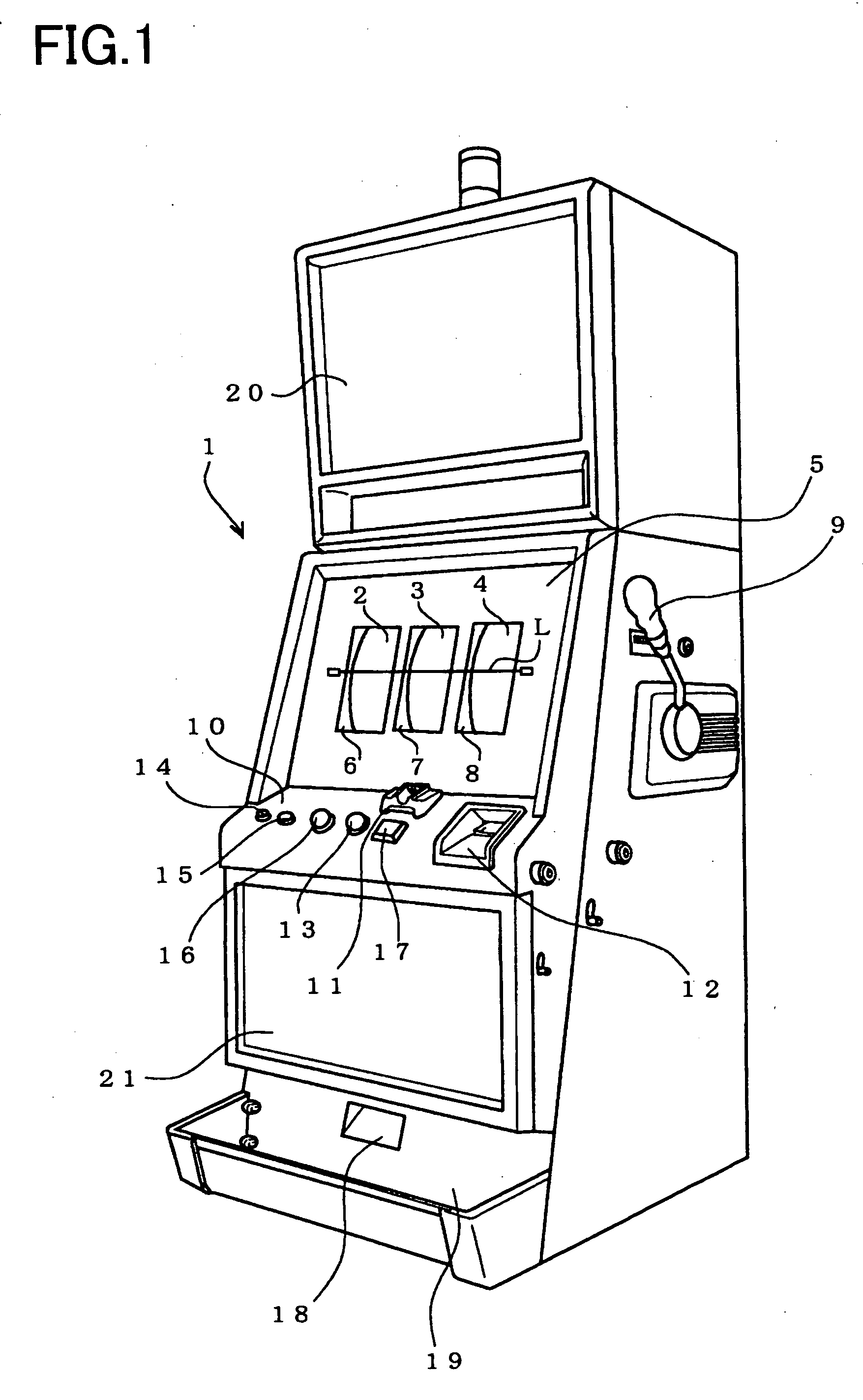
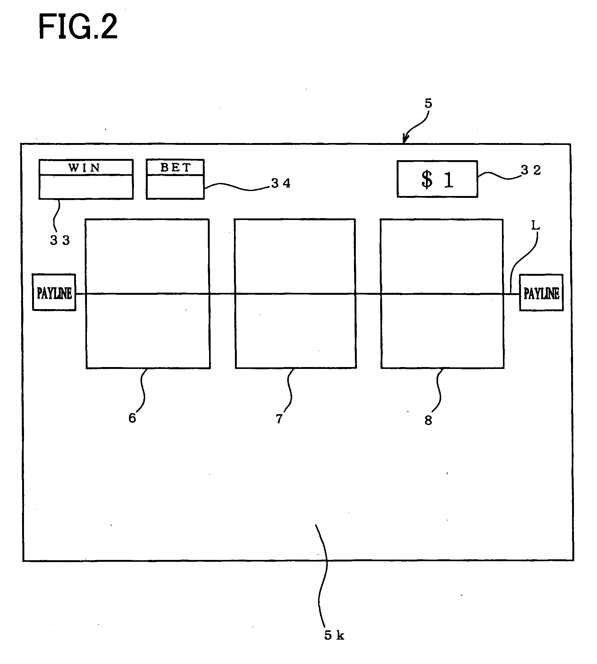
[0023]FIG. 1 is a perspective view of a slot machine 1 in a gaming machine according to the present invention. In a cabinet constructing a central main body of the slot machine 1, three reels comprising a first reel 2, a second reel 3 and a third reel 4 are rotatably arranged. On an outer periphery of each of the reels 2 to 4, a symbol row constructing from a plural kinds of symbols (abbreviated as “the symbol” hereinafter) is described. In front of each of the reels 2 to 4, a reel display window portion 5 is arranged. And in the reel display window portion 5, three display windows 6, 7 and 8 are formed, and three symbols of the symbol row described on the outer periphery of each of the reels 2 to 4 are displayed through each of the display windows 6 to 8, respectively. When a player inserts coins as the game media into the slot machine and operates a start lever 9 arranged at a side of the cabinet, variable display of the symbols is conducted. And on the reel display window portion...

second embodiment

[0048] Next, the slot machine of the second embodiment according to the present invention will be described.

[0049] The slot machine of the second embodiment has the same construction as the slot machine 1 in the above mentioned first embodiment, except for the numerical value input device for setting the denomination which is different from that in the first embodiment.

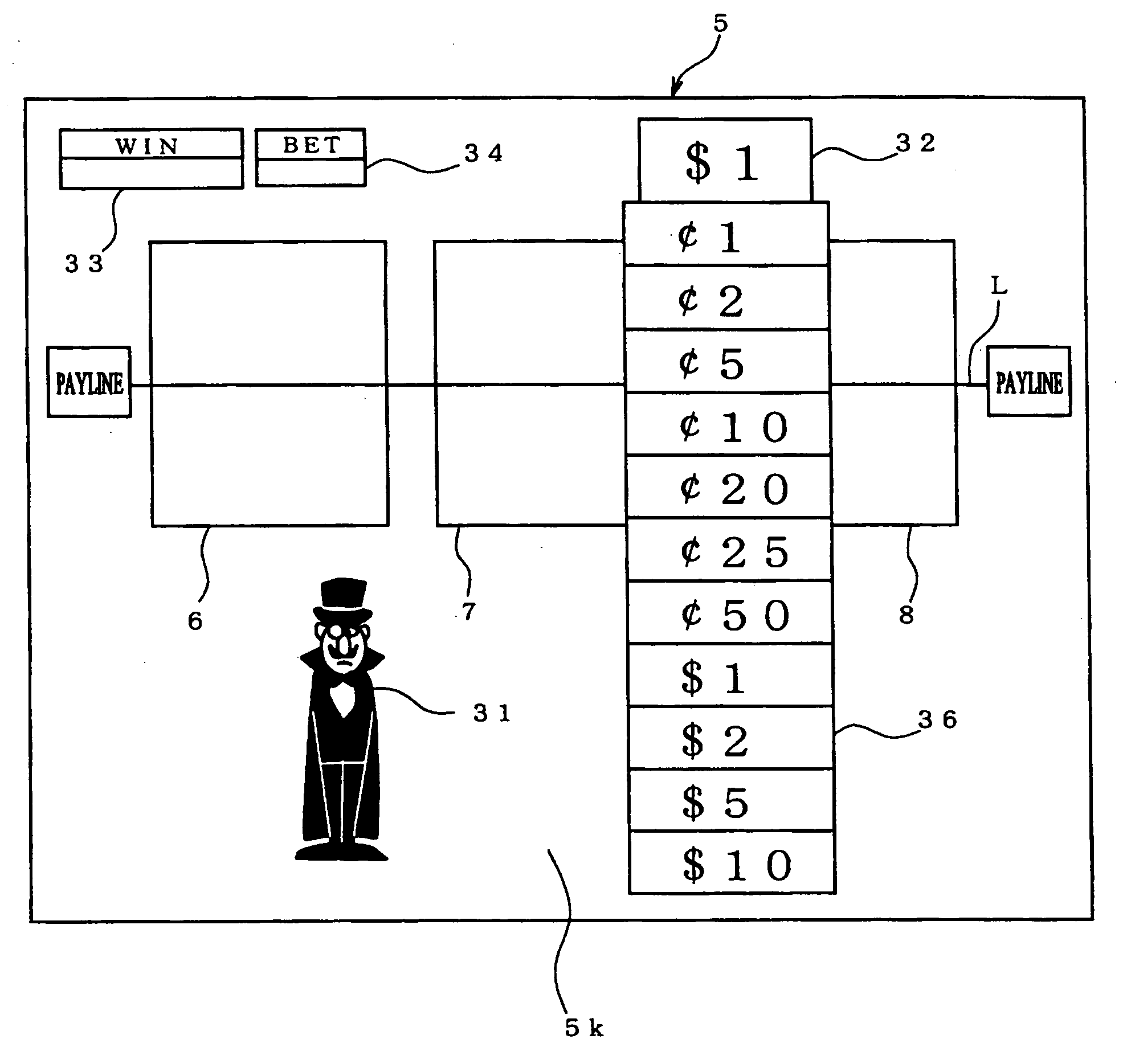
[0050]FIG. 7 is an explanatory view of the reel display window portion on which a denomination selection panel for determining the denomination is provided to determine the denomination, according to the second embodiment. Here, in FIG. 7, the same numbers are added to the members, the elements having the same construction as those in the first embodiment.

[0051] Similar to the above mentioned numerical keypad device 35, the denomination selection panel 36 is constructed from a denomination selection panel image displayed on the liquid crystal display panel 5d and a predetermined area of the touch panel 5k correspond...


PUM


Abstract

In the slot machine 1, when the touch panel 5k corresponding to the periphery of the denomination display part 32 is touched, the numerical keypad image, which constructs the numerical keypad device 35 in cooperation with the touch panel 5k, is displayed on the liquid crystal display panel 5d and input operation of voluntary denomination value through the numerical keypad device 35 is activated. After the sum is input through the numerical keypad device 35, if the player operates the start lever 9 or the spin switch 13 or the MAX BET switch 17, the numerical keypad image disappears. The denomination is recognized by the main CPU 42. Next, when the bet number is directed through operation of the 1-BET switch 16 or the MAX-BET switch 17, the sum calculated by multiplying the denomination with the bet number is set as the betted money. And based on the operation of the start lever 9 or the spin switch or the MAX BET switch 17 by the player, rotation process of the reels 2 to 4 is done, thereby the slot machine game is started.

Description

CROSS-REFERENCE TO THE RELATED APPLICATION(S) [0001] This application is based upon and claims a priority from the prior Japanese Patent Application No. 2003-352222 filed on Oct. 10, 2003, the entire contents of which are incorporated herein by reference. This application is related to a co-pending U.S. application entitled “GAMING MACHINE”, filed on the same date as this application. The co-pending application is expressly incorporated herein by reference. BACKGROUND OF THE INVENTION [0002] 1. Field of the Invention [0003] The present invention relates to a gaming machine in which a game is conducted by betting game media stored therein. [0004] 2. Description of Related Art [0005] Conventionally, as such kind of the gaming machine, it is, for example, well-known a slot machine disclosed in Unexamined Japanese Patent Publication No. 2001-120716. On a switch panel of the slot machine shown in the above reference, there are provided bet buttons through which a player determines a bet ...

Claims


Application Information

Patent Timeline
IPC IPC(8): G02F1/133A63F5/04G07F17/32
CPCG07F17/3262G07F17/3211
Inventor INAMURA, YUKINORI
Owner UNIVERSAL ENTERTAINMENT CORP
Learn More