
Apparatus and method for laser power control

Inactive Publication Date: 2005-04-21
MEDIATEK INC
View PDF11 Cites 27 Cited by
  • Summary
  • Abstract
  • Description
  • Claims
  • Application Information

AI Technical Summary

Benefits of technology

[0014] A major advantage of the present invention is the ability to accurately maintain constant laser power levels in high-speed recording without requiring special, width-extended laser pulses which may possibly damage the optical disc, especially in high-density recording.
[0015] These and other objectives of the claimed invention will no doubt become obvious to those of ordinary skill in the art after reading the following detailed description of the preferred embodiment, which is illustrated in the various figures and drawings.

Problems solved by technology

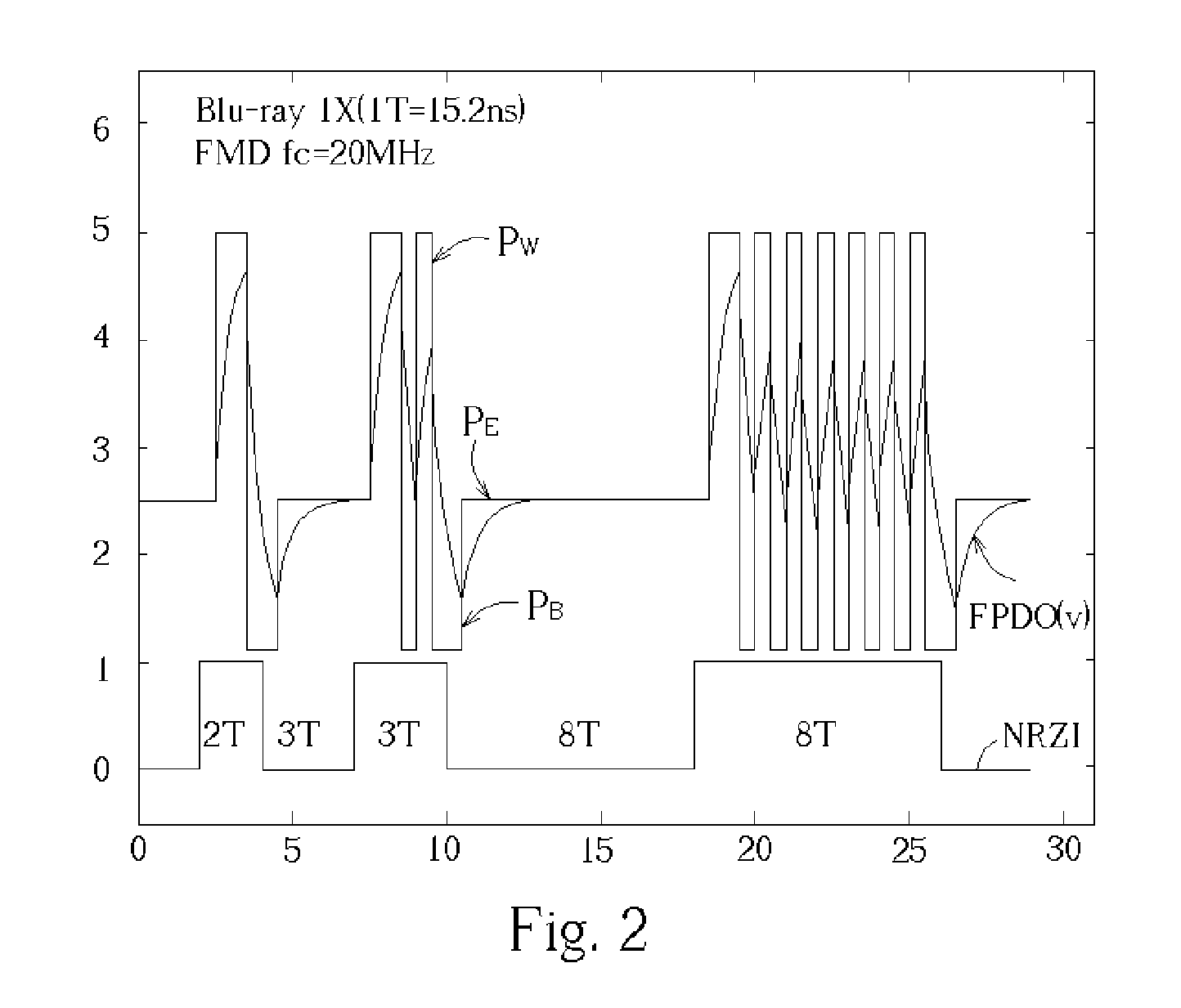
However, high cost or practical manufacturing techniques limit the bandwidth of the FMD such that the FMD output cannot achieve a settled level during high-speed recording pulses.
U.S. Pat. No. 4,307,469, issued to Casper et al. and incorporated herein by reference, discloses another method for laser power control but again requires the use a photodiode fast enough to produce an electrical replica of the optical pulse data stream, which vastly increases the costs and may not be possible regardless of costs during high-speed recording.
However, the 100 MHz FMD response time is still not fast enough for higher speed recordings, such as a 12× as shown in FIG. 4.
Moreover, if an FMD with a bandwidth of 20 Mhz is used for high-speed recording (e.g. 12×), then it is impossible even to control the erase power since the FPDO does not achieve a settled level during the entire recording period as shown in FIG. 5.
The method is not suitable for high-speed, high-density recordings with narrow track pitch where cross-erase or cross-write easily occur when the recording pulse width is too large.

Method used


Image

  • Apparatus and method for laser power control
  • Apparatus and method for laser power control
  • Apparatus and method for laser power control

Examples


Embodiment Construction

[0028] The Blu-ray Disc, Rewritable Format, version 1.0 defines physical data allocation and linking as shown in FIG. 6. A data recording contains a sequence of recording unit blocks. Each recording unit block has a Run-in area and a Run-out area. No data is recorded in the Run-in and Run-out areas. In the Run-in area and the Run-out area (not shown in detail) an optional Automatic Power Control (APC) area is defined for possible application of laser power control. The present invention presents an apparatus and a method of controlling the laser power utilizing the APC area.

[0029]FIG. 7 provides a block diagram of a preferred optical recording apparatus 100 according to the present invention. The apparatus 100 comprises a laser diode (LD) 125 for generating a light pulse according to a current or voltage supplied by a LD driver 120. An FMD 130 detects the power of the light pulse and outputs an FMD output, also known in the art as a Front Photodiode Output (FPDO). The FPDO is trans...


PUM


Abstract

A high-speed optical disc recording apparatus includes a laser diode for generating multi-pulse light pulses and a photodiode outputting a measured power of the light pulses. An NRZI pattern encoder generates a predetermined power control pattern causing a write strategy generator to generate write strategy to a laser diode driver such that the laser diode outputs a multi-pulse having a fixed-duty ratio with two power levels. The measured power is averaged with a low-pass filter, is sampled and held, and is calibrated according to the fixed-duty ratio. The calibrated held average output of the measured power of the light pulses is compared with predetermined present levels to control the laser diode driver output voltage.

Description

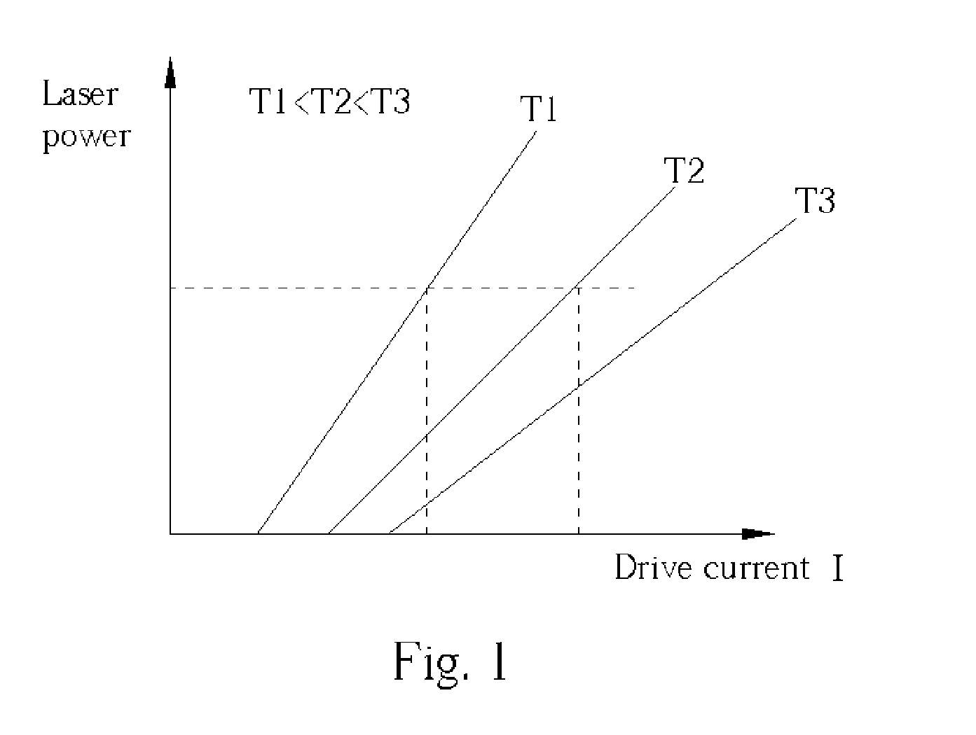
BACKGROUND OF INVENTION [0001] 1. Field of the Invention [0002] This invention relates to automatic power control in an optical recording apparatus. More specifically, a device and method for controlling laser power during high-speed recording in the optical recording apparatus is disclosed. [0003] 2. Description of the Prior Art [0004] During a recording by an optical disc apparatus, a laser diode is used to selectively crystallize a phase-change material comprised by the optical disc. Uniformity in crystallization throughout the optical disc requires uniformity in laser power. However, as shown in FIG. 1, the actual laser power decreases with the same drive current when the temperature increases, necessitating Automatic Power Control (APC). [0005] U.S. Pat. No. 4,685,097, issued to Henk van der Put and included herein by reference, offers one prior art approach to APC. The patent discloses a laser power control in optical recording drives which compares a preset voltage level with...

Claims


Application Information

Patent Timeline
IPC IPC(8): G02B26/02G11B5/09G11B7/00G11B7/0045G11B7/006G11B7/125
CPCG11B7/1263G11B7/0062
Inventor CHEN, CHIH-YUAN
Owner MEDIATEK INC
Learn More