
Stereoscopic display device and display method

a display device and stereoscopic technology, applied in the field of stereoscopic display devices and display methods, can solve the problems of difficult to make a discrimination between the presence and absence of beams converging difficult to be put in a practical use, and difficult to distinguish between the presence and absence of beams at a viewing distan

Inactive Publication Date: 2005-04-21
KK TOSHIBA
View PDF13 Cites 63 Cited by
  • Summary
  • Abstract
  • Description
  • Claims
  • Application Information

AI Technical Summary

Benefits of technology

[0014] The present invention has been made in view of these circumstances, and an object thereof is to a stereoscopic display device where, while suppressing moire or color moire, an aspect ratio of a pixel is set to 1 and simultaneously pixels constitute a square arrangement, and a resolution or an image quality is not changed largely even when switching is performed between a flat image display and a stereoscopic image display.

Problems solved by technology

As a stereoscopic motion picture display device of such a type, there is known one using a principle of holography, which is difficult to be put in a practical use.
In an actual design, particularly, in a case that there are many pixels, however, the difference between the image plane and the focal plane is in a range of 0.1 mm or less, even if there is no aberration, which not only makes it difficult to make a discrimination therebetween regarding precision but also makes it difficult to make a discrimination between presence and absence of beam converging at a viewing distance.
However, when the number of parallaxes is set in this manner, there occurs a problem that color moire appears because a period of color of a color filter and a period of the parallax barrier along a horizontal direction are close to each other.
As means for solving such a problem, there is proposed a method for shifting the number of parallaxes from the multiple of 3, but the aspect ratio of the effective pixel deviates from 1 in the method, which results in need for converting an image.
However, it is a difficult problem that a aspect ratio of pixels is 1 and the pixels constitute a square arrangement for suppressing moire or color moire and attaining matching with a fast image processing, color data or information for each parallax is prevented from lacking, or a deviation in color distribution is canceled.
In the conventional stereoscopic display devices, there is still a problem that, when switching is performed between a flat image (two-dimensional) display and a stereoscopic image (three-dimensional) display, a resolution varies largely and an image quality at a time of flat display lowers due to deviation of a color distribution or the like.

Method used


Image

  • Stereoscopic display device and display method
  • Stereoscopic display device and display method
  • Stereoscopic display device and display method

Examples


first embodiment

(First Embodiment)

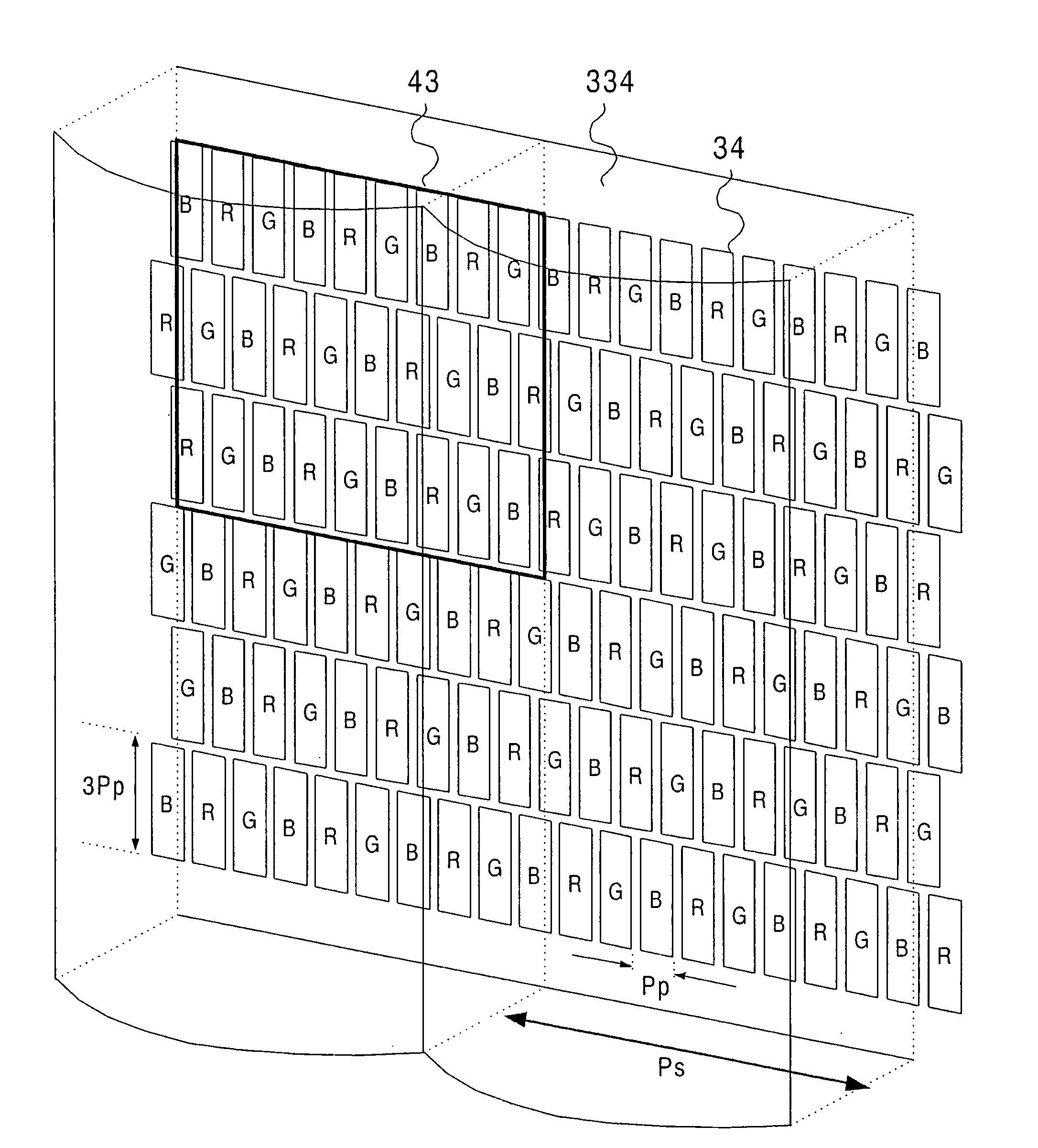
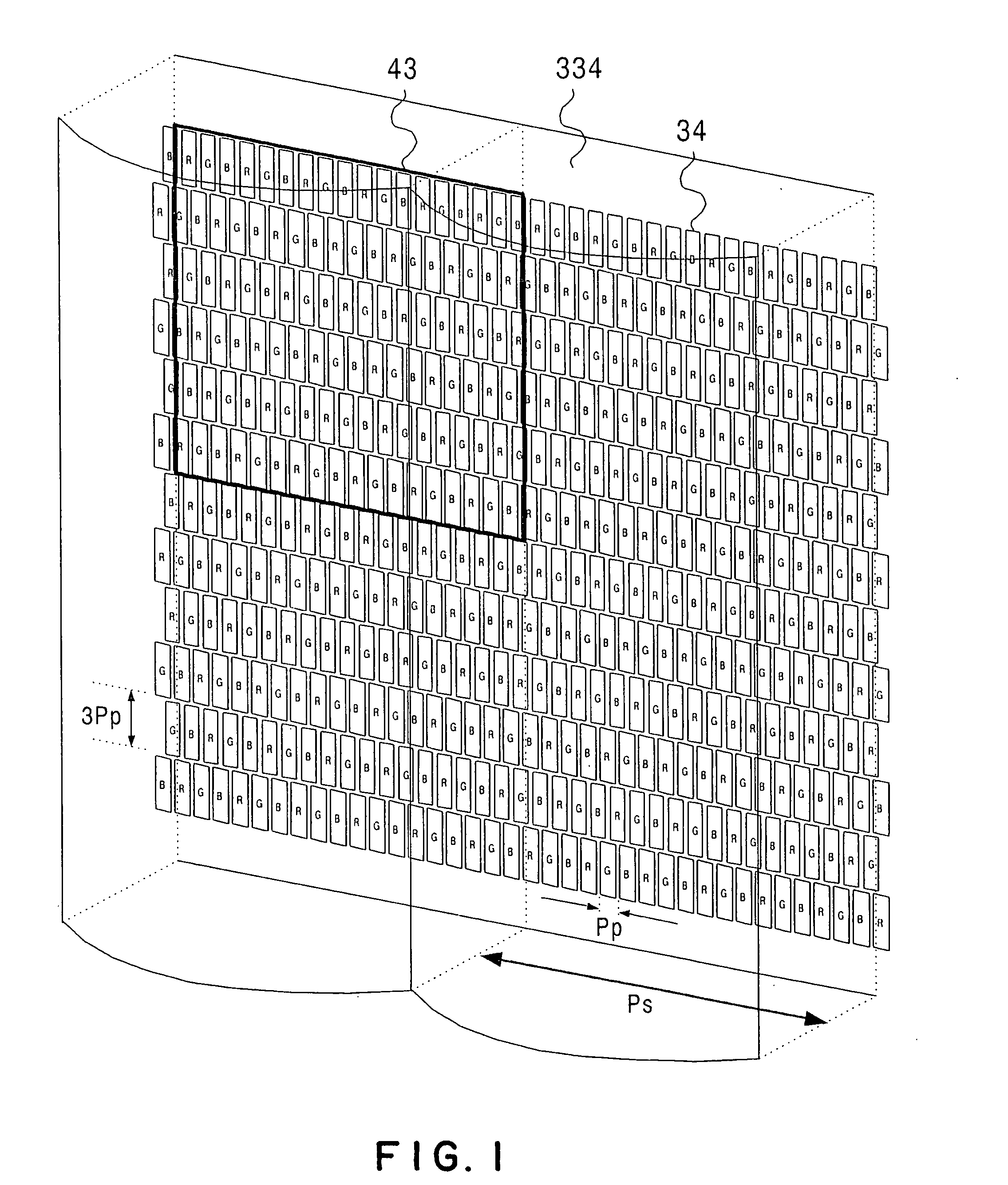
[0061]FIG. 1 is a perspective view schematically showing a constitution of a stereoscopic display device according to a first embodiment of the present invention.

[0062] In such a stereoscopic display device as shown in FIG. 1, a lenticular sheet 334 constituted of cylindrical lenses having an optical aperture extending in a vertical direction is arranged as a beam controlling element at the front of a display plane of a flat parallax image display portion such as a liquid crystal panel. Since the optical aperture is neither oblique nor stepwise but it constitutes a straight line in a vertical direction, a pixel arrangement at a stereoscopic display time can easily be set to a square arrangement. Pixels 34 with an aspect ratio of 3:1 are arranged straightly in one line manner, and the respective pixels 34 are arranged such that red (R), green (G) and blue (B) are alternately positioned laterally in the same line on the display face. FIG. 5 and FIG. 6 are plan views...

second embodiment

(Second Embodiment)

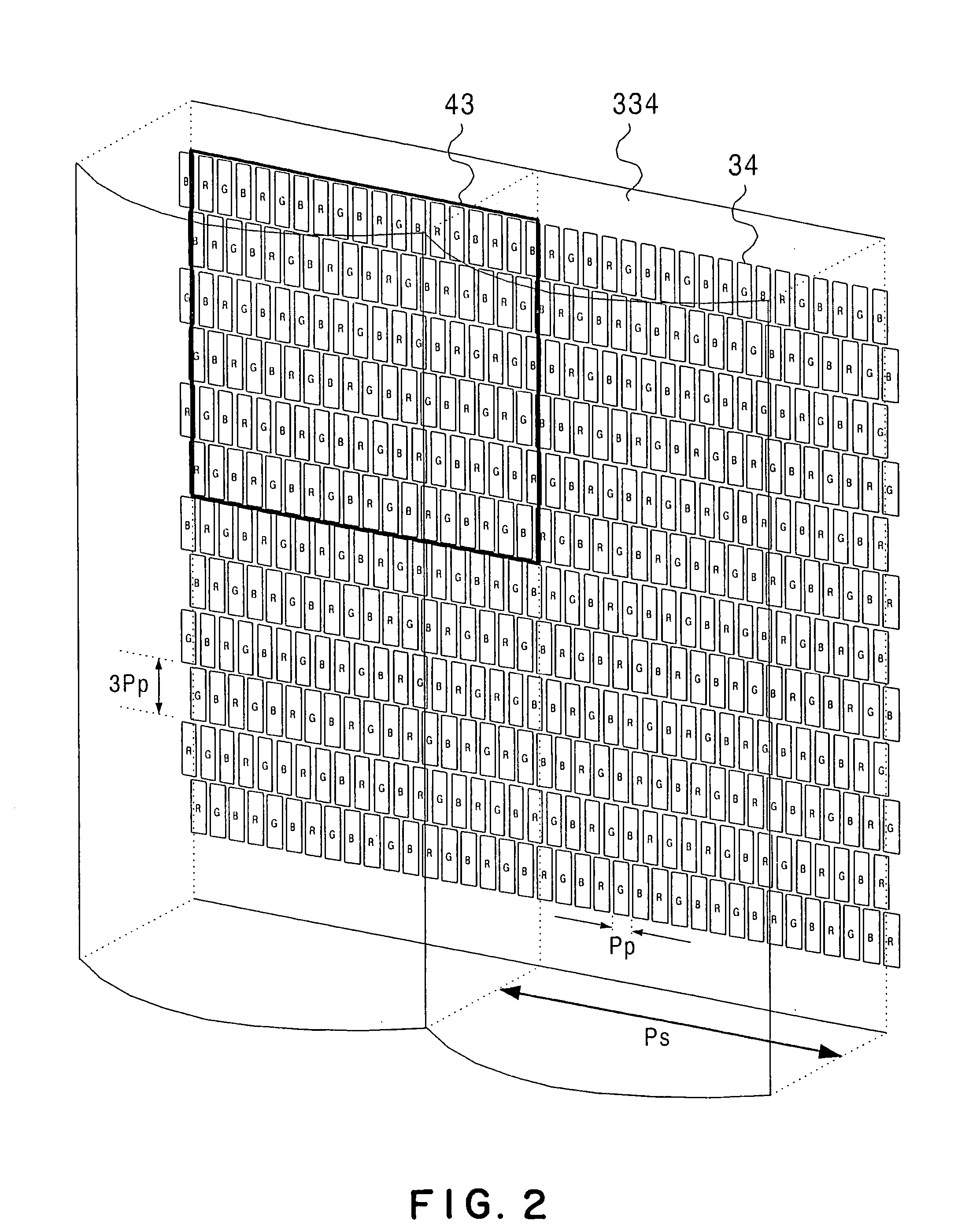
[0096]FIG. 21 is a perspective view schematically showing a constitution of a stereoscopic display device according to a second embodiment of the present invention.

[0097] In such a stereoscopic display device as shown in FIG. 21, a lenticular sheet 334 comprising cylindrical lenses whose optical apertures extend vertically, which serves as a beam controlling element, is disposed at the front of a display plane of a flat parallax image display portion such as a liquid crystal panel. Since the optical openings are arranged in a straight line not stepwise but vertically, it is easy to arrange a pixel arrangement in a square arrangement at a stereoscopic display time. Pixels 34 with an aspect ratio of 3:1 are arranged laterally and vertically in a straight manner and in a matrix manner on the display plane, and respective pixels are arranged such that red, green and blue are alternately positioned laterally in the same row and column. This color arrangement is genera...


PUM


Abstract

It is made possible to satisfy such a condition that moire or color moire is suppressed and a fast image processing is made easy and such a condition that sufficient image quality can be obtained both at a flat image display time and at a stereoscopic image display time simultaneously. A vertical period of pixel rows having the pixels arranged in one row in a lateral direction is three times a lateral period of the pixels, the pixels developing red, green and blue are alternately arranged in a lateral direction in the same row, the pixels in one row of two rows adjacent in a vertical direction are arranged such that lateral positions thereof are shifted to the pixels in the other row by ½ of the lateral period of the pixels, the pixels in rows adjacent in the same column through one row interposed therebetween are the pixels developing different colors of red, green and blue, and a pitch of the elemental images is equal to a width of 18n (n=1, 2, 3 . . . ) pieces of the pixels, and a lateral pitch of the beam control element is smaller than the width of the 18n pieces of the pixels.

Description

CROSS-REFERENCE TO RELATED APPLICATIONS [0001] This application is based upon and claims the benefit of priority from the prior Japanese Patent Application No. 2003-315356, filed on Sep. 8, 2003 in Japan, the entire contents of which are incorporated herein by reference. BACKGROUND OF THE INVENTION [0002] 1. Field of the Invention [0003] The present invention relates to a stereoscopic display device and a display method. [0004] 2. Related Art [0005] As a stereoscopic image or motion picture display device allowing display of a motion picture, so-called “a three-dimensional display”, ones of various systems have been known. In recent years, particularly, a demand for a display device of a flat panel type employing a system where dedicated eyeglasses or the like are not used is increasing. As a stereoscopic motion picture display device of such a type, there is known one using a principle of holography, which is difficult to be put in a practical use. A system where a beam controlling...

Claims


Application Information

Patent Timeline
IPC IPC(8): G02B27/00G02B30/27G02B30/30G09G3/00G09G5/00H04N13/00H04N15/00
CPCG09G2300/0443H04N13/0404H04N13/0409G02B27/2214H04N13/0422H04N13/0447G02B27/0025H04N13/0415H04N13/305H04N13/324H04N13/31H04N13/317H04N13/351G02B30/27G02B30/30
Inventor SAISHU, TATSUOFUKUSHIMA, RIEKOTAIRA, KAZUKIHIRAYAMA, YUZO
Owner KK TOSHIBA
Learn More