Eureka AIR delivers breakthrough ideas for toughest innovation challenges, trusted by R&D personnel around the world.

Light emitting diode lamp

a diode lamp and light-emitting technology, applied in the field of lamp devices, can solve the problems of led lamps, inability to use other flash lights, and inability to emit ligh

Inactive Publication Date: 2005-04-14
CHEN YUEH FU
View PDF13 Cites 74 Cited by
  • Summary
  • Abstract
  • Description
  • Claims
  • Application Information

AI Technical Summary

Benefits of technology

[0003] The goal of the present invention is to replace the original light sources with LED lamps in conventional lamp settings designed for fluorescent lamps, incandescent bulbs, and the bulb-based flash lights.
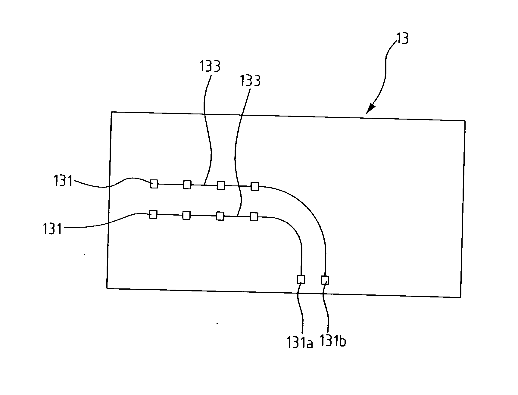
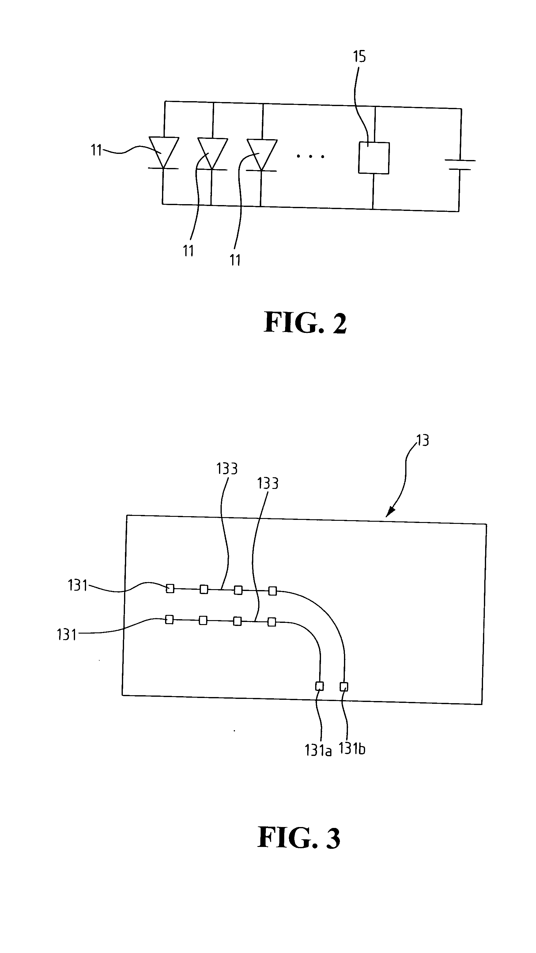
[0004] To achieve the aforementioned purpose, the present invention provides an LED lamp, comprising a plurality of LEDs, a circuit board for soldering said LEDs, a connecting base. The circuit board includes a plurality of solder points, each for soldering an LED, and a conductive line to electrically connect the soldered LEDs. The connecting base is electrically connected to the conductive line of said circuit board. The connecting base is also us...

Problems solved by technology

Wherein the LED lamp, due to the restriction of its special structure, cannot be used with other flash lights originally designed for using W bulbs.

Method used


Image

  • Light emitting diode lamp
  • Light emitting diode lamp
  • Light emitting diode lamp

Examples


first embodiment

[0017]FIG. 4 shows the circuit shown in FIG. 2. It is an embodiment of the present invention in the bulb-based light sources, including the regular incandescent bulbs and the bulb-based flash light. The column 17 in this embodiment has the shape of a short cylinder column. The circuit board 13 is accordingly shaped as a flat plate, horizontally housed in the column 17. The connecting base 15 is located at the bottom of the column 17, so the physical structure of the embodiment is similar to that of the conventional regular incandescent bulbs, or flashlight bulbs.

second embodiment

[0018]FIG. 5 shows the circuit shown in FIG. 2. It is an embodiment of the present invention in the fluorescent light sources, for example, to replace the existing fluorescent tubes. The column 17 in this embodiment has the shape of a long cylinder tube. The circuit board 13 is accordingly shaped as a long strip, vertically housed in the column 17. The connecting base 15 is located at the bottom of the column 17, so that the physical structure of the embodiment is similar to that of a conventional fluorescent light source.

[0019]FIG. 6 shows a variation of the embodiment shown in FIG. 5. The difference lies in that the LEDs are placed on one side only in this design.

[0020]FIG. 7 shows the front view of the connecting base in the embodiments of FIGS. 4, 5, and 6. FIGS. 8A to 8E show the front view of the embodiments of the connecting base used in other types of socket settings. The column 17 used in the present invention can be made of plastic to form various transparent or non-trans...


PUM


Abstract

The present invention is to replace the original light sources with LED lamps in conventional lamp settings designed for fluorescent lamps, incandescent bulbs, and the bulb-based flash lights. It provides an LED lamp, comprising a plurality of LEDs, a circuit board for soldering said LEDs, a connecting base. The circuit board includes a plurality of solder points, each for soldering an LED, and a conductive line to electrically connect the soldered LEDs. The connecting base is electrically connected to the conductive line of said circuit board. The connecting base is also used to mount in the conventional lamp socket and make electrical connection. The connecting base is a column for encompassing the circuit board, wherein said circuit board is shaped according to the shape of the column, and the position of connecting to the column is designed according to the use in the preferred embodiments, such as fluorescent lights, incandescent bulbs, and bulb-based flash lights.

Description

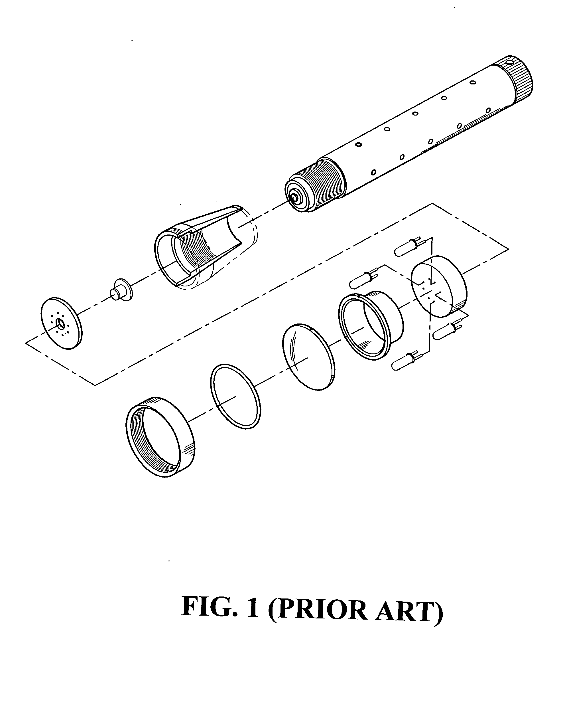
FIELD OF THE INVENTION [0001] This invention relates to the field of lamp devices for lighting sources, and more particular to a high efficiency lamp employing light emitting diodes (LED). BACKGROUND OF THE INVENTION [0002] As the recent development and utilization of high illumination light emitting diodes (LED), it is economically feasible for mass production of these devices. Hence, there have been applications using LEDs as light sources. The prior art shown in FIG. 1 uses a lamp setting designed for incorporating LEDs as the light source for a special flash light. Wherein the LED lamp, due to the restriction of its special structure, cannot be used with other flash lights originally designed for using W bulbs. The present invention provides an LED lamp that can be used directly with the conventional flash lights. In addition, the said LED lamp can also be used in the conventional lamp setting designed for using fluorescent lamps. SUMMARY OF THE INVENTION [0003] The goal of the ...

Claims


Application Information

Patent Timeline
IPC IPC(8): F21K99/00
CPCF21Y2101/02F21Y2111/005F21K9/135F21K9/232F21Y2115/10F21Y2107/30
Inventor LO, CHIN-FENG
Owner CHEN YUEH FU
Why Eureka
Eureka Blog
Learn More