
Adaptive temperature dependent feedback clock control system and method

a clock control and temperature-dependent technology, applied in the field of processor systems, can solve the problems of permanent damage to video graphics circuitry, limited method, and video graphics circuitry tend to generate more hea

Active Publication Date: 2005-03-31
ATI TECH INC
View PDF15 Cites 80 Cited by
  • Summary
  • Abstract
  • Description
  • Claims
  • Application Information

AI Technical Summary

Problems solved by technology

As the operating frequency of the clock signal increases, the video graphics circuitry tends to generate more heat.
However, such a method is limited to a safety mechanism for preventing the junction temperature from exceeding the maximum established junction temperature that may otherwise cause permanent damage to the video graphics circuitry.
Reprogramming of the phase lock loop may result in abruptly changing the clock speed.
Such an abrupt change in clock speed may also result in the video graphics circuitry causing an undesired flicker in a resulting video graphics display.

Method used


Image

  • Adaptive temperature dependent feedback clock control system and method
  • Adaptive temperature dependent feedback clock control system and method
  • Adaptive temperature dependent feedback clock control system and method

Examples


Embodiment Construction

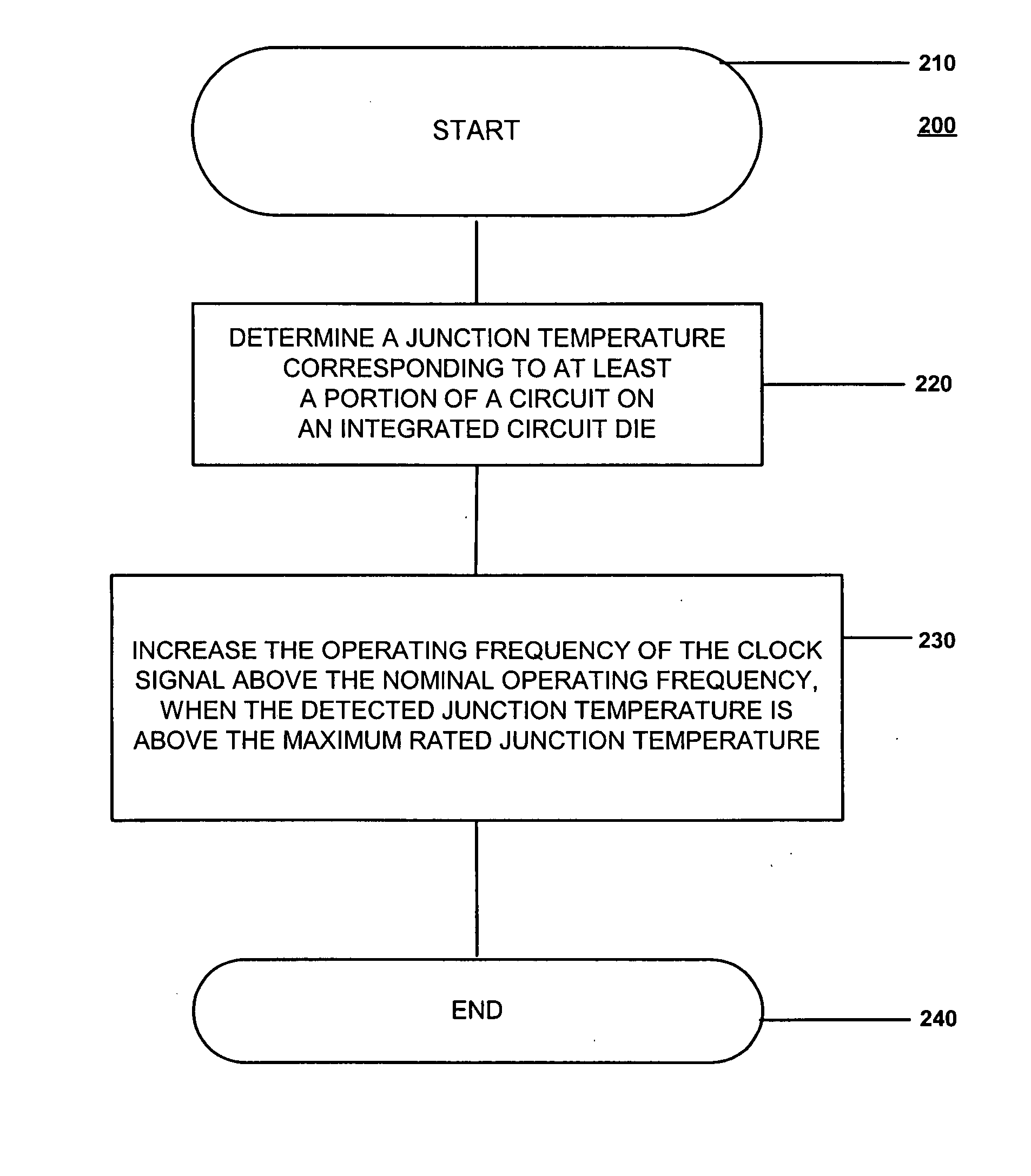
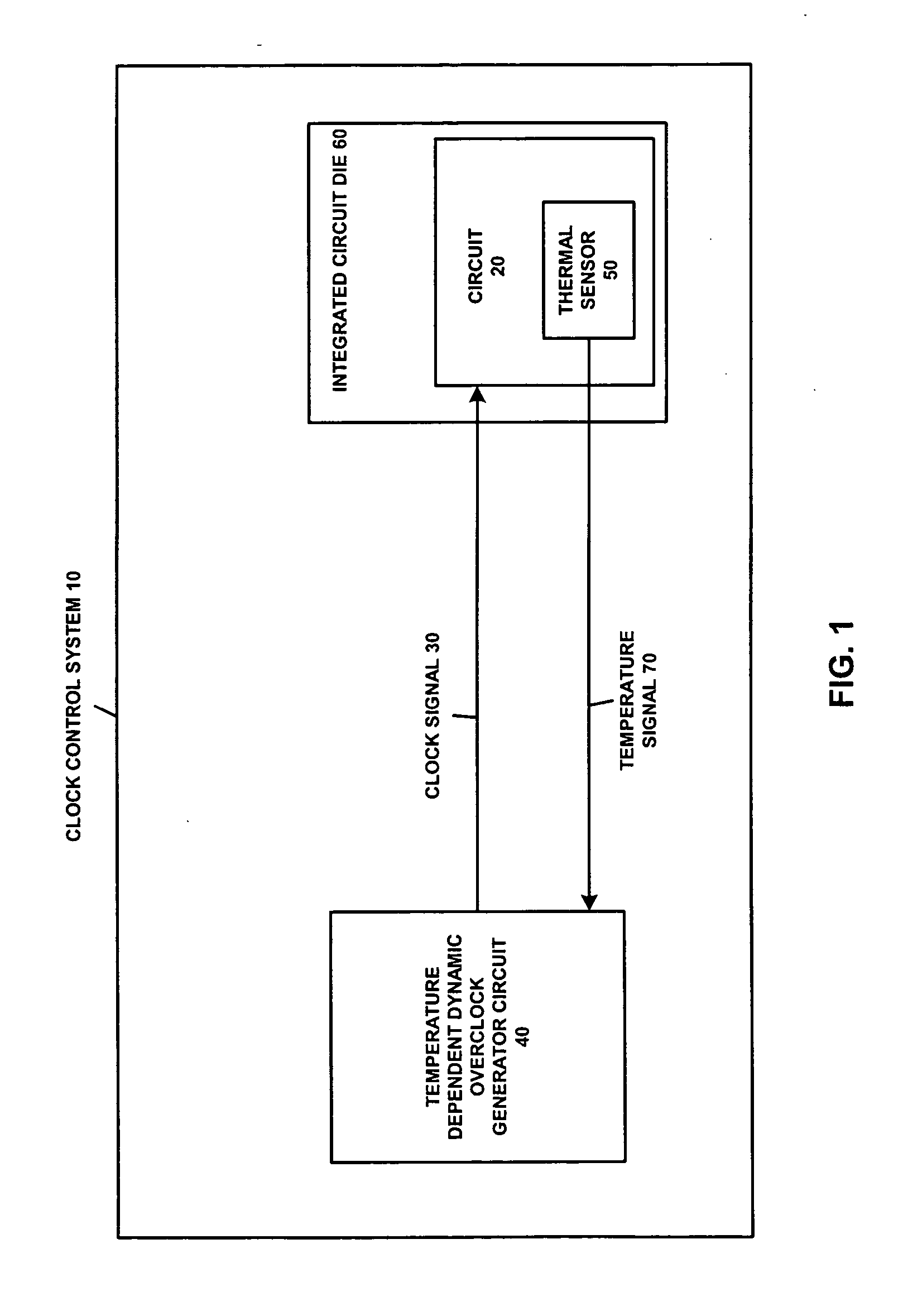
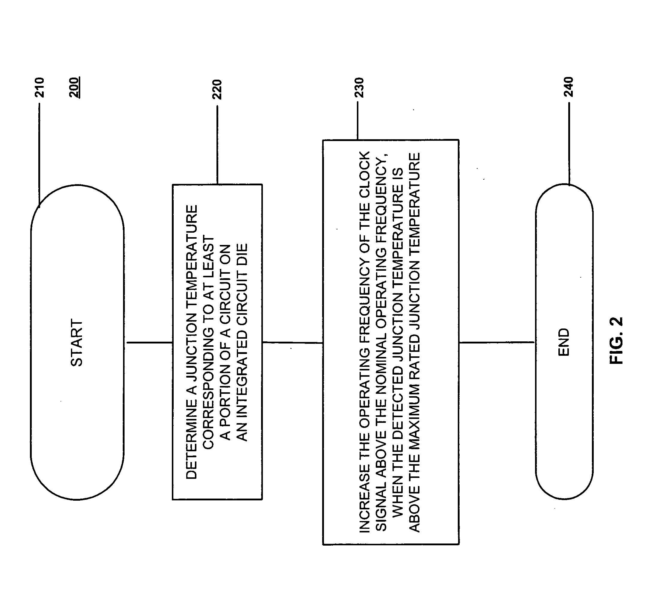
[0014] An adaptive temperature dependent feedback clock control system and method for adaptively varying a frequency of a clock signal to a circuit such that the circuit may operate at a maximum safe operating clock frequency based on a circuit junction temperature. The circuit may be a host processor, a co-processor, such as a graphics co-processor, a memory, or any suitable device for receiving the clock signal. The adaptive temperature dependent feedback clock control system, herein referred to as a clock control system includes a thermal sensor and a temperature dependent dynamic overclock generator circuit. The thermal sensor detects a junction temperature corresponding to at least a portion of the circuit on a semiconductor die. The clock control system adapts the frequency of the clock signal according to the junction temperature by monitoring the circuit junction temperature via the thermal sensor to form a feedback loop. According to one embodiment, the frequency of the clo...


PUM


Abstract

An adaptive temperature dependent clock feedback control system and method for adaptively varying a frequency of a clock signal to a circuit such that the circuit may operate at a maximum safe operating clock frequency based on a circuit junction temperature. The clock control system includes a thermal sensor and a temperature dependent dynamic overclock generator circuit. The thermal sensor detects a junction temperature corresponding to at least a portion of the circuit on a semiconductor die. The temperature dependent dynamic overclock generator circuit varies the clock signal based on the semiconductor die junction temperature, such that the clock signal operates at the highest possible operating frequency associated with the detected junction temperature. The frequency of the clock signal is increased from a first frequency to at least a second frequency and a third frequency if the junction temperature is below a lower junction temperature threshold.

Description

FIELD OF THE INVENTION [0001] The invention relates generally to processor systems and, more particularly, to clock control circuits for processor systems. BACKGROUND OF THE INVENTION [0002] A computer system, and other processor based systems, are known to include a central processing unit, video graphics circuitry, system memory, and other peripheral circuits. In such systems, the central processing unit functions as a host processor while the video graphics circuitry (e.g., a graphics co-processor) functions as a loosely coupled co-processor. By way of example, the video graphics circuitry may be an integrated circuit on a single semiconductor die, such as an application specific integrated circuit (ASIC). Additionally, the video graphics circuitry may include memory, such as, but not limited to, dynamic ram (DRAM). This memory may reside on the same semiconductor die (ASIC) as the video graphics circuitry or it may be separate and connected through board level or package level t...

Claims


Application Information

Patent Timeline
Patent Type & Authority Applications(United States)
IPC IPC(8): G06F1/20
CPCG06F1/206
Inventor BRUNO, JOHNKHODORKOVSKY, OLEKSANDRPANG, ERWINPHAN, GIA
Owner ATI TECH INC
Learn More