
Method for enabling a branch-control system in a microcomputer apparatus

a microcomputer and branch control technology, applied in the direction of micro-instruction address formation, computation using denominational number representation, instruments, etc., can solve the problems of masked rom suffering one major drawback, masked rom can only be written to once, and the processing unit cannot track its progress through a program, etc., to achieve the effect of reducing the amount of hardware required and reducing production costs

Inactive Publication Date: 2005-03-31
MEDIATEK INC
View PDF3 Cites 13 Cited by
  • Summary
  • Abstract
  • Description
  • Claims
  • Application Information

AI Technical Summary

Benefits of technology

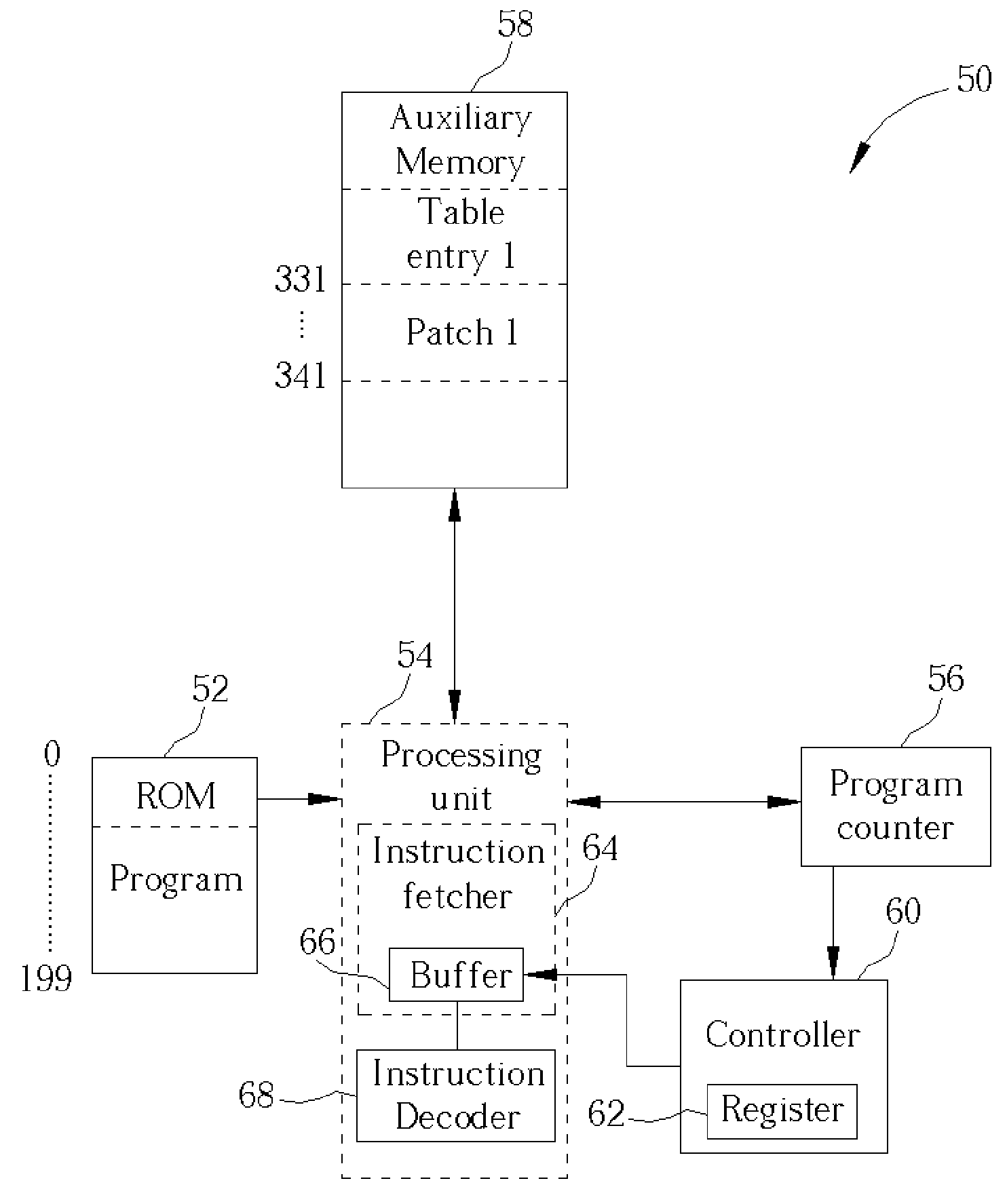
[0018] It is advantageous of the present invention microprocessor apparatus to employ a controller having a register for storing an initializing program count value and an auxiliary memory for storing patches along with a table contained a replacement program count value for each patch. By using the controller and auxiliary memory, the present invention can reduce the amount of hardware necessary to implement a branch off the ROM and in some cases, the amount of time needed to make a branch. In turn, production costs can be lowered.

Problems solved by technology

An important consequence of this fact is that a processing unit is unable to track its progress through a program.
However, the masked ROM suffers one major drawback: the masked ROM can only be written to once.
As a result, any changes that need to be made after the masked ROM has been programmed cannot be made.
Despite careful testing and debugging, there are times when the code in the ROM needs to be altered after the ROM has been programmed-usually because some erroneous sections of code are found.
However, for reasons stated above, the code inside of a written masked ROM cannot be changed.
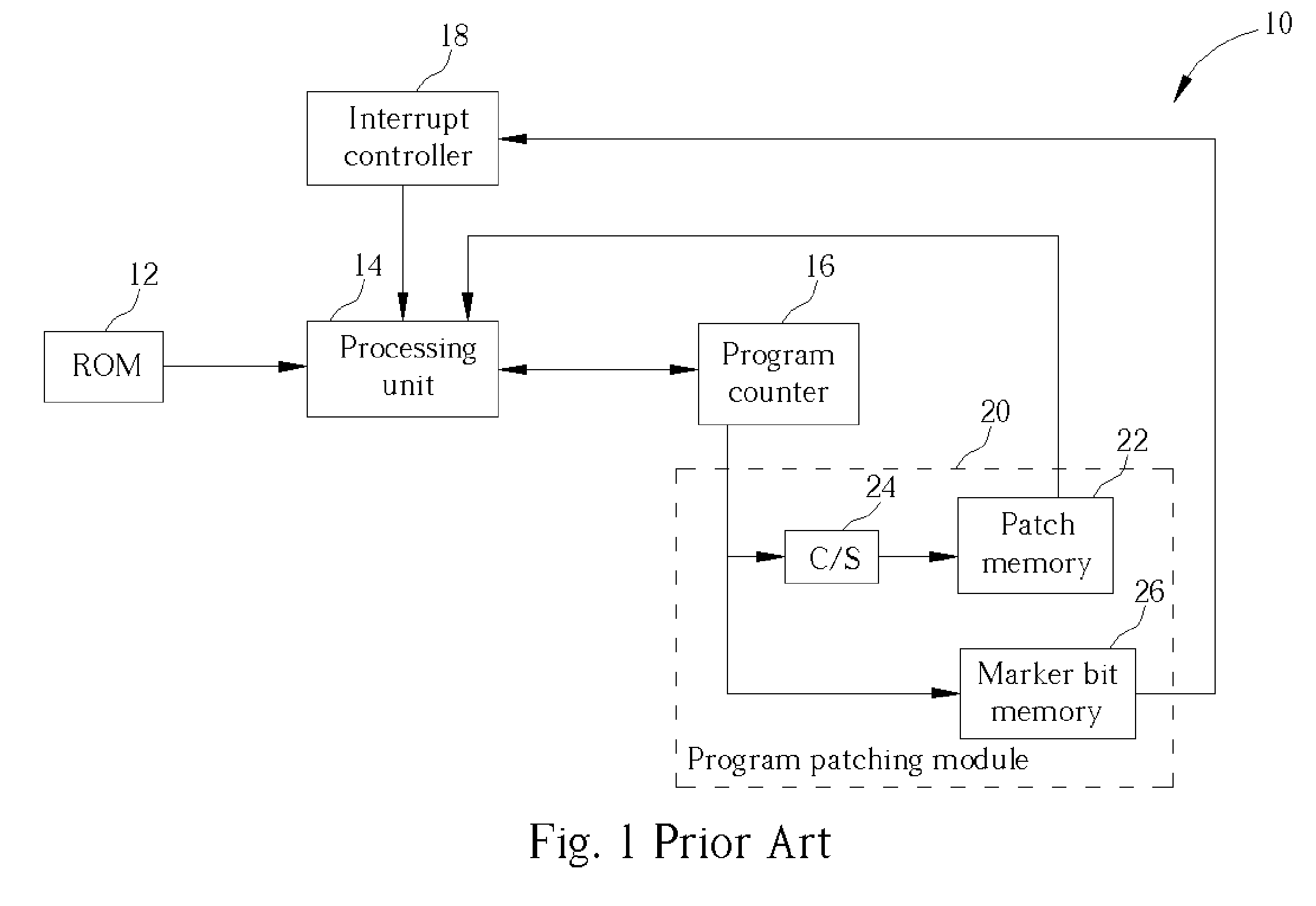
A larger size means a larger silicon die is needed to manufacture the chip, which leads to increased production cost.
Consequently, many of the marker bits would be of a value of 0 and therefore, wasted.
In the end, this solution faces similar problems as the first prior art in that production costs are higher because of the increase in the chip die size.

Method used


Image

  • Method for enabling a branch-control system in a microcomputer apparatus
  • Method for enabling a branch-control system in a microcomputer apparatus
  • Method for enabling a branch-control system in a microcomputer apparatus

Examples


Embodiment Construction

[0024] Please refer to FIG. 3. FIG. 3 shows a diagram of a microcomputer apparatus 50 according to the present invention. The microcomputer apparatus 50 comprises a ROM 52 for storing a first program, a processing unit 54 for executing instructions, a program counter 56 for storing a program count value, an auxiliary memory 58 for storing patches and a table of corresponding replacement count values, and a controller 60 for storing and comparing an initializing count value to the program counter's 56 count value and issuing an indirect branch instruction with an index in response to a match.

[0025] In a preferred embodiment, the processing unit 54 comprises an instruction fetcher 64 that has a buffer 66 and an instruction decoder 68. The instruction fetcher 64 retrieves instructions according to the program counter 56 and stores instructions in the buffer 66. The instruction decoder 68 increments the program counter 56 and decodes instructions stored in the buffer 66. The controller...


PUM


Abstract

According to the claimed invention, the controller is a chip with a memory connected to the program counter of a microcomputer apparatus. The chip is capable of comparing the value of the program counter against the value stored inside its own memory and issuing an indirect branch instruction with an index upon a match. The indirect branch instruction is capable of searching a table for an entry corresponding to the index and replacing the value of the program counter with the value of the entry in the table.

Description

BACKGROUND OF INVENTION [0001] 1. Field of the Invention [0002] The invention relates to a branch-control system for a microcomputer apparatus and more particularly, to a branch-control system for a ROM-programmed microcomputer apparatus. [0003] 2. Description of the Prior Art [0004] Microcomputer apparatuses are ubiquitous in today's world. Found in everything from cellular phones to DVD players, most electronic devices posses some form of a microcomputer apparatus in the form of a processing unit executing instructions stored in memory. In addition, almost all of these microcomputer apparatuses have a processor executable program stored in a ROM-type memory and hence, can be considered a ROM-programmed processing unit (ROM-programmed processing unit can be considered as any processing unit that executes instructions stored in a ROM Read Only Memory). [0005] A main function of a processing unit of the microcomputer apparatus is to execute instructions. An important consequence of t...

Claims


Application Information

Patent Timeline
IPC IPC(8): G06F7/38G06F9/00G06F9/26G06F9/38G06F9/42G06F9/44G06F15/00
CPCG06F9/328G06F8/66G06F9/30061
Inventor HSIEH, YAO-HUANG
Owner MEDIATEK INC
Learn More