
Power flow controller responsive to power circulation demand for optimizing power transfer

a power flow controller and power circulation technology, applied in the direction of electric variable regulation, process and machine control, instruments, etc., can solve the problems of affecting reducing the efficiency of power transmission lines, so as to reduce the prone to human error and simplify the role of power system operators in selecting power dispatch strategies.

Inactive Publication Date: 2005-03-31
RENESSELAER POLYTECHNIC INST
View PDF5 Cites 65 Cited by
  • Summary
  • Abstract
  • Description
  • Claims
  • Application Information

AI Technical Summary

Benefits of technology

The disclosed embodiments overcome the deficiencies of conventional systems and methods by providing a power flow controller responsive to power circulation demand for optimizing power transfer in a power network. When a power flow controller operates at its rated capacity, the coupled voltage-sourced converters in the power flow controller can no longer regulate from-bus voltage setpoints, line power flow setpoints, or both. In such cases, the power flow controller switches to a power circulation setpoint control without exceeding the rated capacities of the voltage-sourced converters. By replacing a number of control variables having complex interactions with a single circulating power control variable, the role of a power system operator in selecting a power dispatch strategy is greatly simplified, thus resulting in a dispatch strategy that is more efficient and less prone to human error than conventional dispatch strategies, where the system operator may have to specify multiple control variables in real-time under post-contingency conditions.

Problems solved by technology

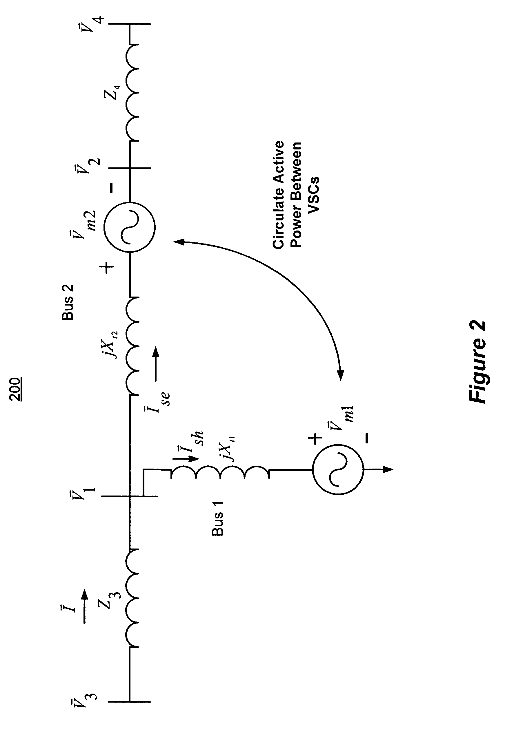
For UPFC, IPFC and GUPFC devices, however, a reliable power transfer at rated capacities is more complex because of the ability of these controllers to circulate active power.
One problem with operating a FACTS device at its rated capacity is the heightened risk of voltage collapse.
Voltage collapse occurs when a power controller attempts to serve more load than the output voltage of the controller can support.

Method used


Image

  • Power flow controller responsive to power circulation demand for optimizing power transfer
  • Power flow controller responsive to power circulation demand for optimizing power transfer
  • Power flow controller responsive to power circulation demand for optimizing power transfer

Examples


Embodiment Construction

Overview of UPFC Architecture

While the following description is based on a UPFC architecture, the disclosed embodiments can be extended to other types of FACTS devices having two or more coupled VSCs, including without limitation IPFC and GUPFC devices.

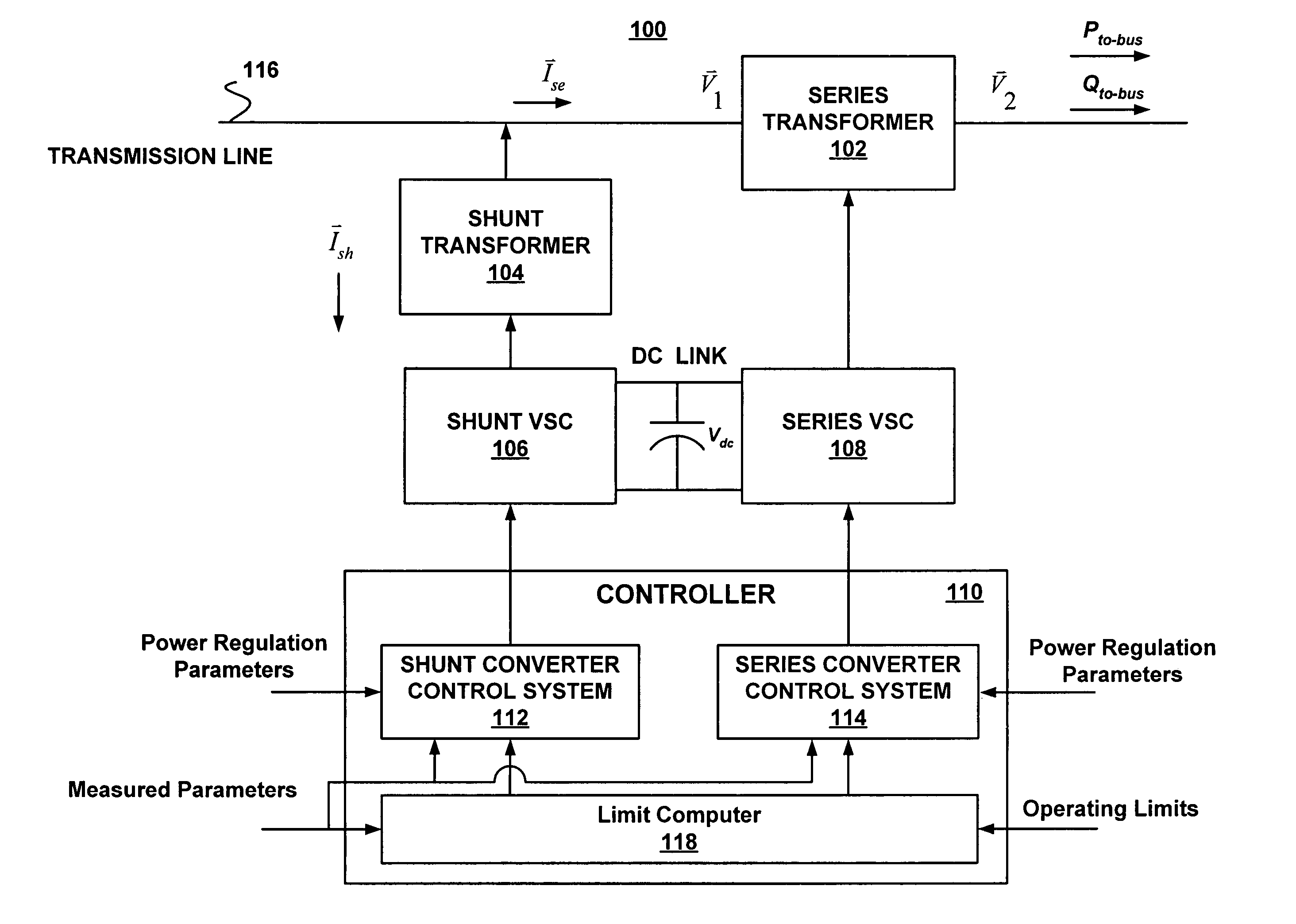
FIG. 1 is a block diagram showing the main elements of a UPFC system 100, which is responsive to power circulation demand. The UPFC system 100 includes a series insertion transformer 102, a shunt transformer 104, a shunt VSC 106, a series VSC 108, a controller 110 and a limit computer 118. In some embodiments, the shunt VSC 106 and the series VSC 108 are coupled back-to-back and operated from a common dc link voltage Vdc, which is typically provided by a dc storage capacitor. This arrangement functions as an ideal ac-to-ac power converter in which the real power can freely flow in either direction on a transmission line 116 between the ac terminals of the VSCs 106 and 108. In addition, each VSC 106, 108, can independently generate...


PUM


Abstract

A power flow controller responsive to power circulation demand for optimizing power transfer is disclosed. When a power flow controller operates at its rated capacity, it can no longer regulate from-bus voltage set-points, line power flow set-points, or both. In such cases, the power flow controller switches to power circulation set-point control without exceeding the rated capacities of the voltage-sourced converters in the power flow controller. Power-voltage (PV) curves associated with voltage stability analysis for maximizing power transfer can be generated and stored for use with a power flow controller operating in automatic power flow control mode.

Description

TECHNICAL FIELD The invention relates generally to the control of power flow in electric power transmission lines, and more particularly to power flow dispatch strategies for optimizing power transfer. BACKGROUND Flexible Alternating Current Transmission Systems (FACTS) are used for the dynamic control of voltage, impedance and phase angle of high voltage alternating current (ac) electrical power transmission lines. Since the concept of FACTS was introduced, a family of power electronic equipment has emerged for controlling and optimizing the flow of electrical power in electrical power transmission lines. This equipment makes use of large rating (4500 V to 6000 V, 4000 A to 6000A) gate turn-off thyristors (GTOs) in high power inverter configurations that can be controlled to behave as three-phase sinusoidal voltage sources. FACTS controllers are operated synchronously with the transmission line and can be connected either in parallel, producing controllable shunt reactive current...

Claims


Application Information

Patent Timeline
IPC IPC(8): H02J3/06H02J3/18
CPCG05F1/70H02J3/06Y02E40/18Y02E10/563H02J3/1814Y02E10/56Y02E40/10
Inventor CHOW, JOE H.WEI, XUANFARDANESH, BRUCEEDRIS, ABDEL-ATY
Owner RENESSELAER POLYTECHNIC INST
Learn More