
Heart valve repair apparatus and methods

a heart valve and apparatus technology, applied in the field of repair and replacement of heart valves, can solve the problems of chords bursting, the distance between the attachment of leaflet edges is constantly changing, and the safety margin is small, so as to improve the function of the left ventricular wall, prevent the bulging of the posterior wall of the heart, and be reliable and permanent.

Inactive Publication Date: 2005-03-31
SPENCE PAUL A
View PDF50 Cites 291 Cited by
  • Summary
  • Abstract
  • Description
  • Claims
  • Application Information

AI Technical Summary

Benefits of technology

[0015] A device constructed in accordance with the invention would preferably fix the annular diameter, the chordal length and the point of chordal fixation in the ventricle. In this way, the invention provides a more reliable and permanent solution to the problems associated with the valve repair. Furthermore, it would be easy to perform by most surgeons. A small incision could be made in the annular attachment of the poorly supported anterior leaflet and the post passed through this incision. The support member would then be attached to the native annulus. Flexible tensile members, such as artificial or natural chords would then be attached from the post to the unsupported edge of the leaflet and adjusted by pulling them to length and fixing them. In the case of replacement chords, they are preferably fixed at the level of the support member. Devices could include posterior posts, anterior posts or both. A variety of possibilities exist for modified structures, including multi-forked posts or surgeon-created posts. It would also be preferable to provide chordal patterns to attach the posts to the leaflets and to develop a quick connect system for attachment of the chords to the leaflet edges. Adjustability of the system will be important in many cases for fine tuning.
[0016] Another form of the invention comprises a support member, which may be an annuloplasty ring or other support structure, and at least one post. A first chord gripping member is coupled with the post and configured to grip at least one of the chords and thereby fix the length of the chord between the first gripping member and the leaflets to support and align the leaflets for coaptation during operation of the valve. In the case of mitral valve repair, the post extends into the left ventricle taking origin from the posterolateral commisure. In a preferred embodiment, one gripping member traps the chords to the anterior leaflet in such a way that their distance from the leaflet edge is precisely fixed. A second post and gripping member can do the same for the posterior leaflet. The surgeon would then confirm that the gripping members had captured the chords precisely so that the leaflets meet exactly in systole. If there would be any doubt about this coaptation or should there be a fear of late failure due to chordal rupture, the native chords could be augmented or replaced by an array of replacement chords suspended from the posts and attaching to the leaflet edge. One may also postulate improved left ventricular function from the device since the bulging of the posterior wall of the heart will be prevented by the tethering of the chords which are trapped in the device.
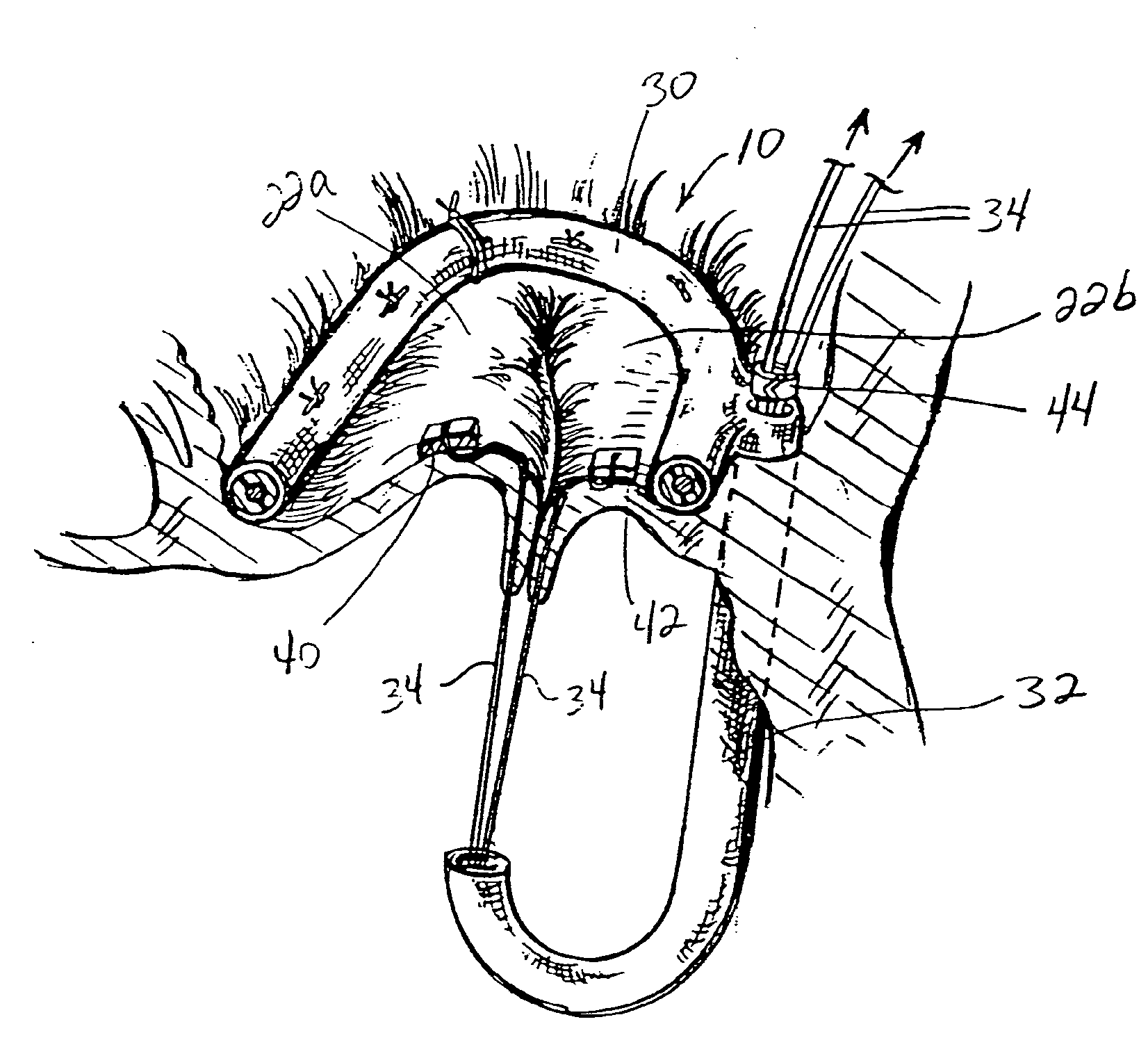
[0017] The various devices of this invention are formed of biocompatible materials including, but not limited to, exposed biocompatible metals, fabric covered metal or polymer, exposed polymer, or any other biocompatible artificial or biologic material. The various devices of this invention may also be incorporated into a full replacement heart valve structure again formed from any biocompatible material for cases necessitating full replacement of the valve. In these cases, the replacement valve is fully supported in a position ensuring accurate coaptation of the valve leaflets and less stressful interaction of the valve leaflets with each other as well as with the valve commisures.
[0018] Another aspect of the invention provides a device for supporting a heart valve in a patient comprising a support structure configured for attachment to the heart valve annulus and a post connected to opposite sides of the support structure and configured to extend from one side of the annulus to another side thereof. This modifies the shape of the annulus, for example, to correct for ischemic condition. The post may be contained substantially in the same plane as the support structure and valve annulus or may extend substantially out of the plane containing the support structure and valve annulus. If extending substantially in the same plane, the post prevents outward bellowing of the valve leaflets, while if extending substantially out of the plane, the post simply functions to connect and modify the shape of opposite sides of the annulus. The post may be length adjustable to allow variable modification of the annulus and may include additional posts of adjustable length or fixed length. As with other embodiments of the invention, the support structure may comprise a ring-shaped member or one or more discrete support segments.
[0019] As another manner of correcting an ischemic condition, for example, a ring-shaped support member is provided having an asymmetric-shape about two perpendicular axes. Stated more generally, one side of the ring-shaped support member may be of narrower width than an opposite side of the ring-shaped support member. This may or may not be coupled with a slight angling downward of one side of the ring-shaped support member with respect to the opposite side of the ring-shaped support member. These modifications help to close a gap created between the valve leaflets due to conditions such as an ischemic condition.
[0020] In another aspect of the invention, a device is provided for adjusting the distance between a papillary muscle and an annulus of a heart valve. This device comprises a support member configured to be affixed to the annulus of the heart valve and an elongate flexible tensile member having first and second ends with the first end adapted to be fixed to the papillary muscle. A connector is configured to connect with the elongate flexible member and with the support member in a manner allowing adjustment in the length between the papillary muscle and the support member and fixation of the elongate flexible member at a desired length between the papillary muscle and the support member. Generally, this device is useful for setting the critical distance between the papillary muscle and the valve annulus and may be used in preparation for the various valve replacement and repair techniques and devices disclosed herein.

Problems solved by technology

Typically, the contact surface is about 12 mm in a direction perpendicular to the anterior-posterior direction and this provides little margin of safety.
Unfortunately, this anchor point (i.e., the inner wall of the left ventricle) must move with each heartbeat and so the distance between the attachment of the leaflet edges is constantly changing.
Chords may also rupture.
This valve was not suitable for any type of plastic procedure and, accordingly, numerous valve prostheses were developed to replace the entire valve, i.e., the annulus, leaflets and chords.
Recently, it has become apparent that combinations of these two problems are relatively common.
Unfortunately, despite the fact that the leaflet tissue is suitable for retention, mitral repair is performed for less than half of the cases where mitral regurgitation is the problem.
One main problem is that mitral valve repair technology has not kept pace with the change in mitral valve pathology.
Few surgeons or surgical centers are equipped for or capable of performing this type of work on a routine basis.
These rings may appear to be a solution for a variety of problems but are not ideal for many ischemic and degenerative disease conditions.
Despite many attempts, the homograft mitral valve replacement is not an operation which can be performed reliably.
Failures occur because of the unreliability of attachment of the chords to the left ventricle.
However, it is virtually impossible to ensure that the chords are correctly spaced inside the ventricle to produce a competent valve.
Again, the inner surface of the ventricle is a moving surface and it is almost impossible to guarantee that a chord extending from a leaflet edge will be fixed in such a way that the anterior and posterior leaflets are reliably aligned during valve operation.
Various other repair procedures are performed, but these are limited to the removal of leaflet tissue which is poorly supported and to chordal shortening and replacement.
Many valves simply remain unrepaired due to the shortage of acceptable techniques and apparatus.
Despite numerous attempts to produce durable leaflet replacements, none have been found.
The cost of demonstrating the value of a new material is extremely high.
Regulatory issues in this field are the single most expensive factor.
To date, this remains a troublesome variable to the valve repair.
However, the regurgitation often becomes severe after left ventricular ischemia occurs.
This often leaves a degree of mitral regurgitation and mitral stenosis results.

Method used


Image

  • Heart valve repair apparatus and methods
  • Heart valve repair apparatus and methods
  • Heart valve repair apparatus and methods

Examples


Embodiment Construction

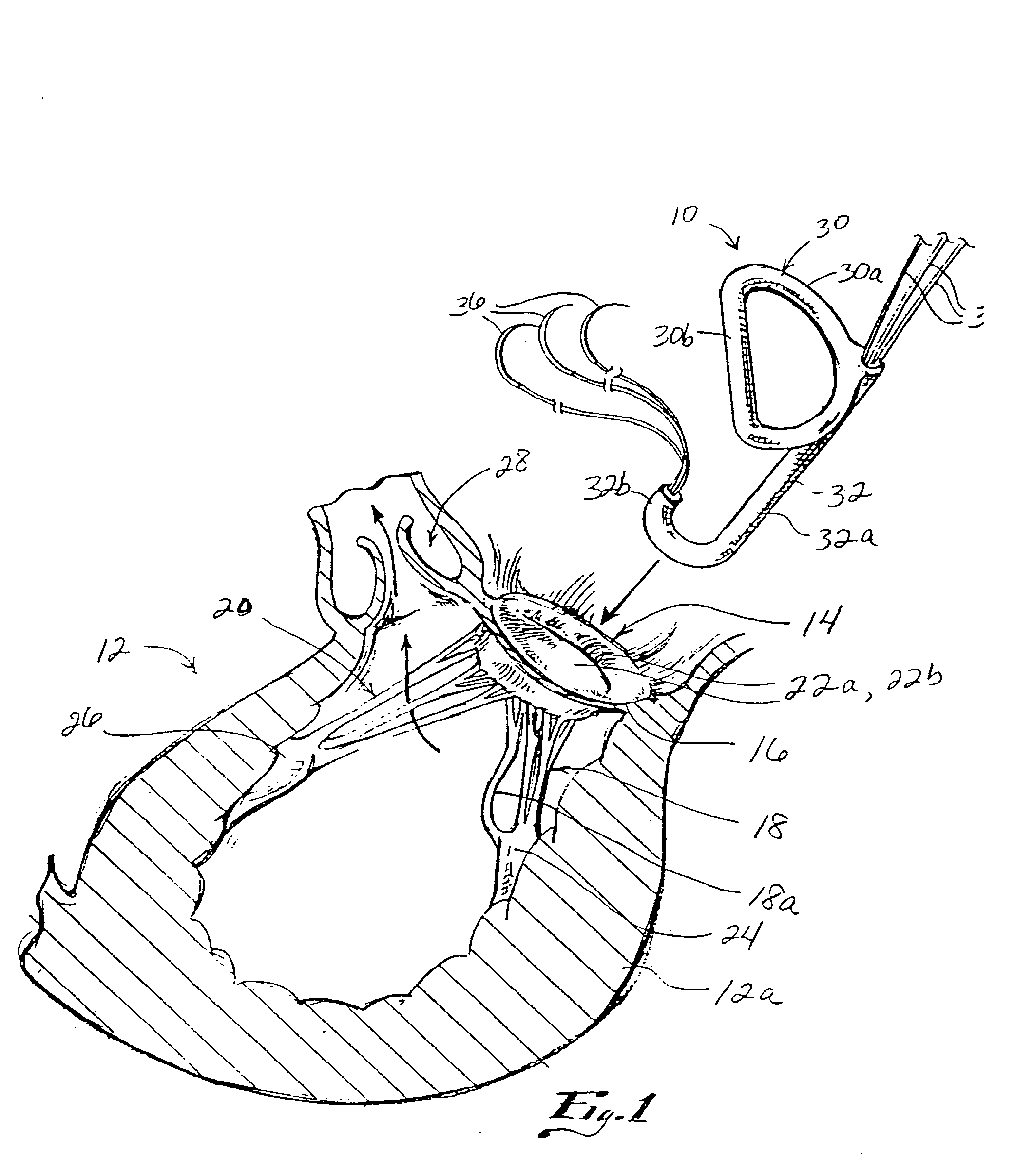
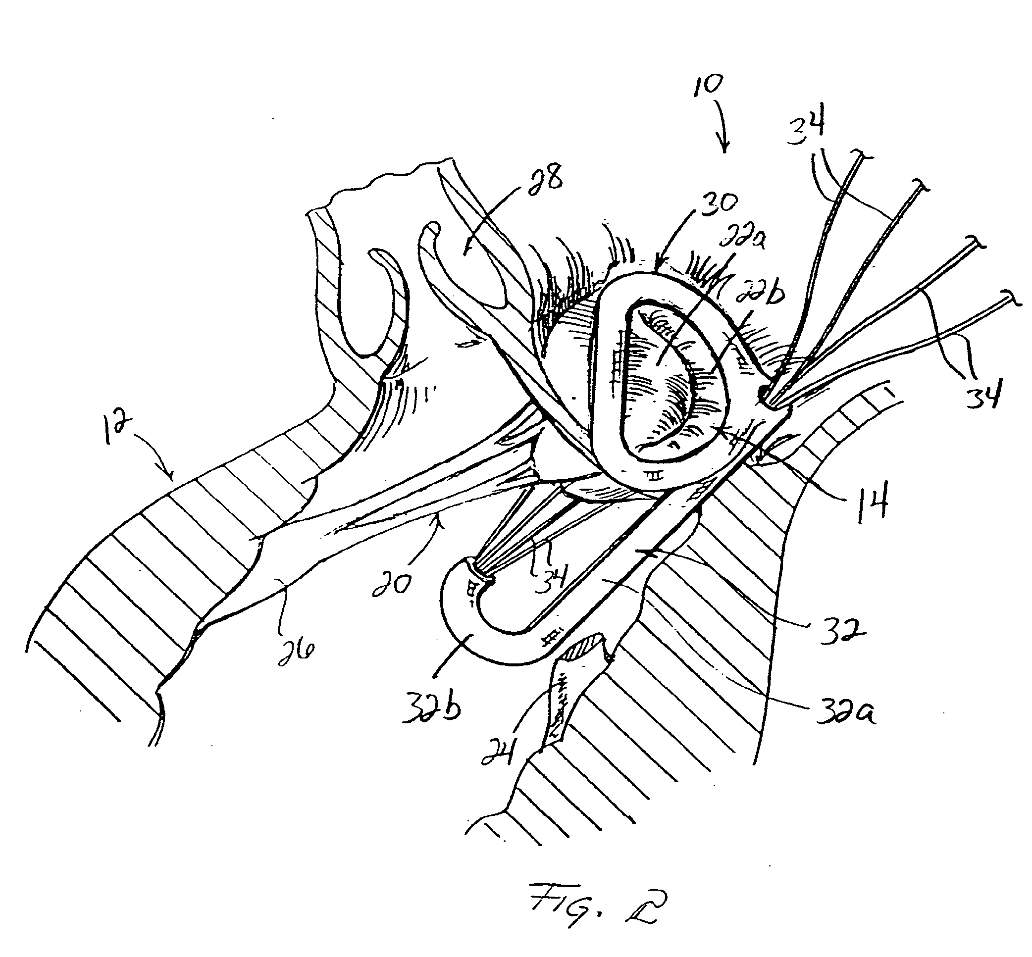
[0059] Referring first to FIG. 1, a device 10 for supporting a heart valve in a patient is shown. In the illustrated example, the left ventricle 12 of a patient's heart is shown in cross section with a mitral valve 14 for supplying blood into the ventricle 12. Mitral valve 14 includes an annulus 16 generally lying in a plane and a plurality of native chordae tendonae or chords 18, 20 respectively connected with a pair of valve leaflets 22a, 22b at one end and papillary muscles 24, 26 at an opposite end. In a normally functioning heart, chords 18, 20 support the valve leaflets 22a, 22b between open and closed positions to selectively allow and prevent blood flow into and out of left ventricle 12. Blood enters left ventricle 12 through mitral valve 14 and is expelled during the subsequent contraction of the heart muscle through aortic valve 28. It will be appreciated that the present invention is applicable to heart valves other than the mitral valve in various of its aspects to be de...


PUM


Abstract

Valve repair apparatus and methods for ensuring proper coaptation and operation of the leaflets of a heart valve. Main aspects of the disclosure relate to devices including a support member configured for attachment to the heart valve annulus, a post extending from the support member away from the plane of the annulus and a connector coupled with the post and configured for attachment to at least one of the leaflets. The various embodiments may include a replacement heart valve connected with the support member for facilitating full replacement as opposed to near repair of an existing native heart valve. Various other devices include support structure and one or more posts connected to opposite sides of the support structure and extending from one side of the valve annulus to another to modify the shape of the annulus.

Description

FIELD OF THE INVENTION [0001] The present invention generally relates to heart valve repair and replacement techniques and apparatus. More specifically, the invention relates to the repair of heart valves having various malformations and dysfunctions. BACKGROUND OF THE INVENTION [0002] The mitral valve depends on adequate apposition or alignment between the anterior and posterior leaflets along a relatively long surface area under high pressure conditions. Typically, the contact surface is about 12 mm in a direction perpendicular to the anterior-posterior direction and this provides little margin of safety. The leaflet margins are attached to numerous fine chords suspended from attachment points along the inner surface of the left ventricle. Although these attachments are often referred to as papillary muscles, there is often a very diffuse arc-shaped attachment for each of the groups of chords to the endocardial surface. Unfortunately, this anchor point (i.e., the inner wall of the...

Claims


Application Information

Patent Timeline
IPC IPC(8): A61F2/24
CPCA61F2/2418A61F2/2445A61F2/2448A61F2230/0034A61F2/2457A61F2/2466A61F2220/0075A61F2/2454A61F2/2463
Inventor SPENCE, PAUL A.
Owner SPENCE PAUL A
Learn More