
Method for communication control and wireless communication system

Inactive Publication Date: 2005-03-31
KK TOSHIBA
View PDF3 Cites 99 Cited by
  • Summary
  • Abstract
  • Description
  • Claims
  • Application Information

AI Technical Summary

Benefits of technology

[0018] An object of the present invention is to provide a method of communication control for interrupting data communication and switching to audio communication during the data communication between a mobile station and a terminal device in a wireless communication system.

Problems solved by technology

That is, when the mobile station is connected with the terminal device through a wire, there is a problem that the connection line is an obstacle when operating the terminal device.
However, in the communication system utilizing short-distance wireless communication based on, e.g., the Bluetooth standard, there is not prepared a procedure concerning a suspension of data communication between the mobile station and the terminal device.
Therefore, when an audio signal is received during data communication, there is a problem that switching to an audio incoming call response cannot be performed by the terminal device.

Method used


Image

  • Method for communication control and wireless communication system
  • Method for communication control and wireless communication system
  • Method for communication control and wireless communication system

Examples


first embodiment

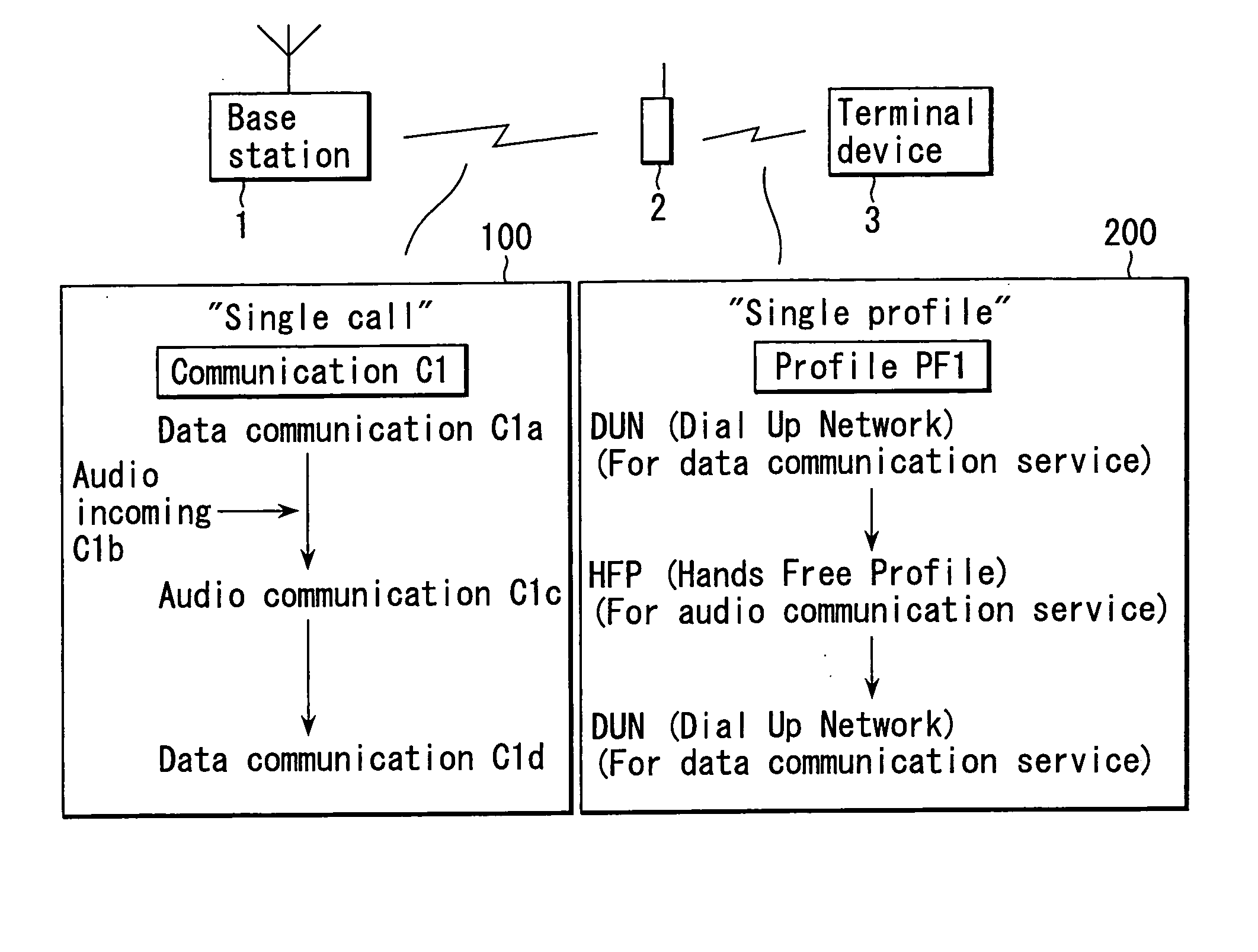
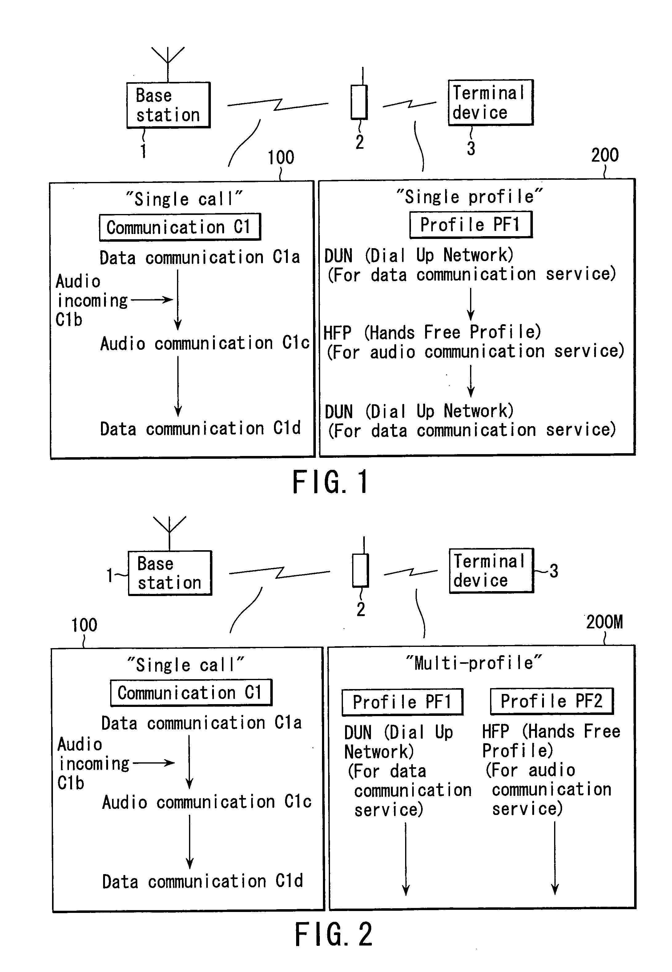
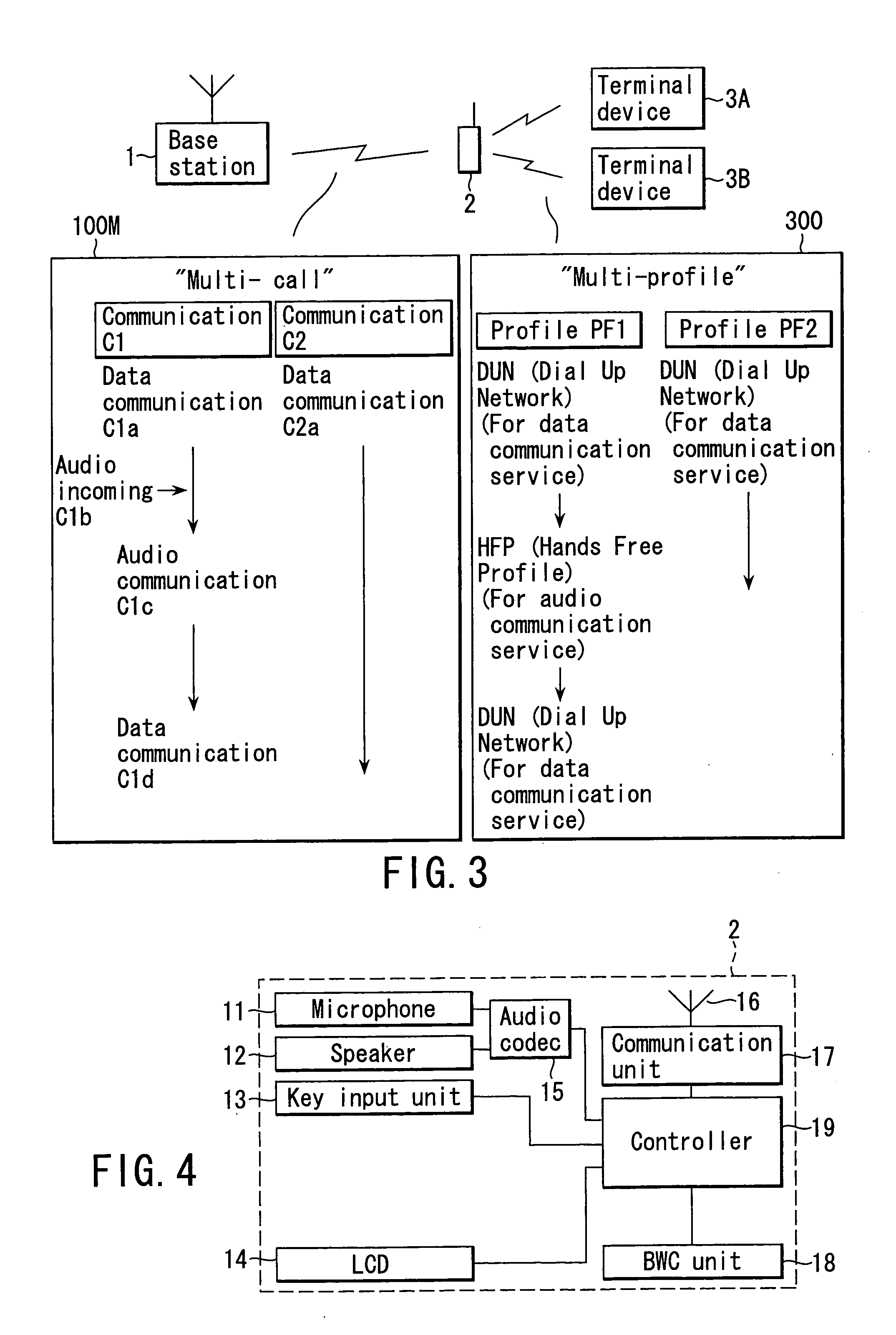
[0079] An operation of a communication system concerning the first embodiment will now be described hereinafter with reference to FIGS. 6 to 8.

[0080] A communication control of this embodiment includes a procedure to notify the terminal device 3 of opening of a session and switch the data communication to the audio communication when there is an audio incoming during reception of the data communication by the mobile station 2.

[0081] The detailed operation of a first mobile communication system depicted in FIG. 1 will now be described with reference to FIGS. 6 to 8.

[0082]FIGS. 6 and 7 show a switching sequence from the data communication to the audio communication in such a mobile communication system as illustrated in FIG. 1. FIG. 8 is a timing chart showing operations of the mobile station 2 and the terminal device 3 with respect to a part of the sequence.

[0083] Here, as described above, the wireless mobile communication is executed between the base station 1 and the mobile sta...

second embodiment

[0141]FIGS. 9 and 10 are views showing timing charts concerning a second embodiment.

[0142] This embodiment includes a procedure that the terminal device 3 notifies the mobile station 2 of a session opening when there is an audio incoming during the data communication.

[0143] A description will now be given as to an operation of this embodiment in the mobile communication system depicted in FIG. 1 with reference to FIGS. 9 and 10.

[0144]FIG. 9 shows a sequence such as an audio incoming response during the data communication in the mobile communication system shown in FIG. 1. FIG. 10 shows a timing chart illustrating operations of the mobile station 2 and the terminal device 3 with respect to a part of the sequence depicted in FIG. 9.

[0145] Differences from the first embodiment will be mainly described hereinafter with reference to FIGS. 9 and 10. It is to be noted that like reference numerals denote parts equal to those in the first embodiment.

[0146] The sequence in FIG. 9 shows a...


PUM


Abstract

There is disclosed a communication control method in a wireless communication system having a base station of a mobile communication system, a mobile station and a terminal device connectable to the mobile terminal through short-distance wireless communication. In this wireless communication system, when an audio incoming call is generated during data communication, the mobile station notifies the terminal device of temporal interruption of the data communication with the terminal device. Upon receiving the temporal interruption of the data communication, the terminal device judges that there is an audio incoming interruption instead of a standard procedure in the regular short-distance wireless communication.

Description

CROSS-REFERENCE TO RELATED APPLICATIONS [0001] This application is based upon and claims the benefit of priority from prior Japanese Patent Application No. 2003-342562, filed Sep. 30, 2003, the entire contents of which are incorporated herein by reference. BACKGROUND OF THE INVENTION [0002] 1. Field of the Invention [0003] The present invention generally relates to a wireless communication system, and more particularly to a communication control method between a mobile station and a terminal device connected through short-distance wireless communication. [0004] 2. Description of the Related Art [0005] In recent years, a development of a mobile communication system as typified by a mobile phone has been advanced in a wireless communication system. [0006] In a mobile communication system, there has been developed a system in which a mobile phone connectable to a base station by wireless is used as a mobile station and a terminal device can perform data communication through the mobile...

Claims


Application Information

Patent Timeline
IPC IPC(8): H04M1/72412H04M1/60H04M11/00H04W76/02H04W88/04
CPCH04M1/6041H04M1/6091H04W88/04H04M2250/02H04W76/023H04M1/7253H04W76/14H04M1/72412
Inventor TAMURA, TOSHIYA
Owner KK TOSHIBA
Learn More