Piston pump

Inactive Publication Date: 2005-03-24
ADVICS CO LTD
View PDF17 Cites 21 Cited by
  • Summary
  • Abstract
  • Description
  • Claims
  • Application Information

AI Technical Summary

Benefits of technology

[0006] In view of the foregoing, an object of the present invention is to provide a piston pump which can be manufactured at low cost and allows a drop in flow resistance of a flow path connecting a suction port and a suction valve.
[0008] In the piston pump, a portion of the flow path connecting the suction port and the suction valve is defined by the plurality of communicating grooves formed on the outer surface of the piston, and the cylindrical seat member externally and fixedly fitted to the piston in a region corresponding to the communicating grooves. This feature allows the piston to be manufactured without involvement of cutting (the piston can be, for example, a forged part, a press-shaped part, or a resin-molded part), thereby reducing the cost of manufacturing the piston. In the piston pump, since a portion of the flow path connecting the suction port and the suction valve is defined by the communicating grooves and the seat member, the size of the flow path is unlikely to be limited. Thus, the flow resistance of the flow path connecting the suction port and the suction valve can be lowered, whereby pump performance can be enhanced.
[0009] The piston pump of the present invention may be configured in such a manner that an annular flange portion extending radially outward is formed on the seat member; and the flange portion holds an annular seal member interposed between the cylinder bore and the seat member and adapted to seal against the cylinder bore and the seat member. In this case, the seat member can also function as a seal-holding member, whereby the piston pump can assume a simple, inexpensive configuration.
[0010] The piston pump of the present invention may be configured in such a manner that the seat member is a resin-molded part; an annular mounting groove is formed on an outer circumferential portion of the seat member; and the annular seal member interposed between the cylinder bore and the seat member and adapted to seal against the cylinder bore and the seat member is fitted into the mounting groove. In this case, the valve port, the valve seat, the annular mounting groove, and the like to be formed on the seat member can be formed when the seat member is formed by means of molding, so that the cost of producing the seat member can be reduced.
[0011] The piston pump of the present invention may be configured in such a manner that a guide portion for guiding axial movement of the piston along the cylinder bore is integrally formed on the seat member. In this case, the guide portion of the seat member can guide the axial movement of the piston, so that smooth axial movement of the piston can be ensured.

Problems solved by technology

In the above-mentioned conventional piston pumps, a portion of a flow path connecting the suction port and the suction valve is formed in the piston by means of cutting, resulting in an increase in the cost of manufacturing the piston.
If a process of removing the burrs is required, the cost of manufacturing the piston will increase further.
Since a portion of the flow path connecting the suction port and the suction valve is formed in the piston, the flow path may fail to be imparted with a sufficiently large size, potentially resulting in an increase in flow resistance of the flow path.

Method used


Image

  • Piston pump
  • Piston pump
  • Piston pump

Examples


first embodiment

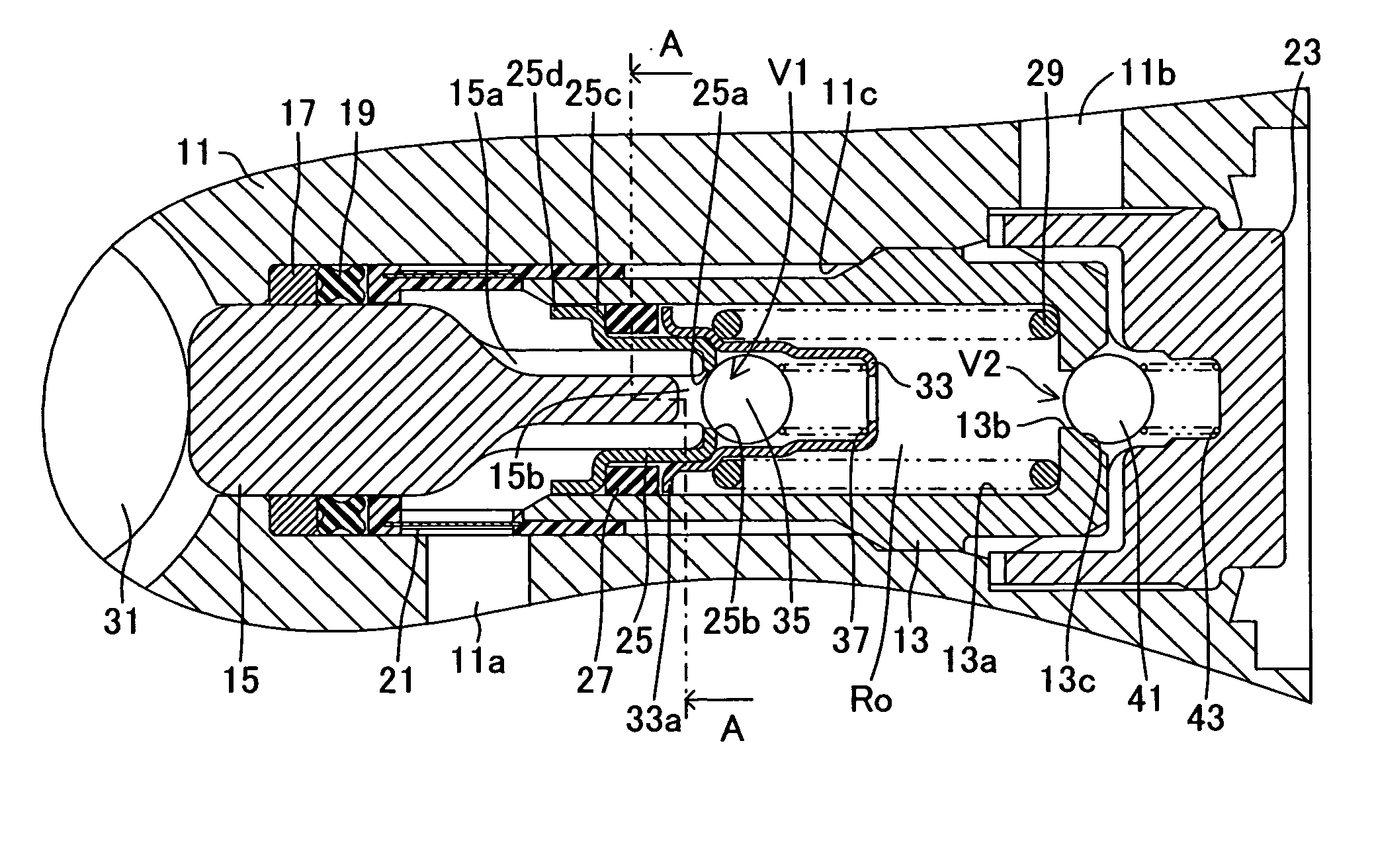
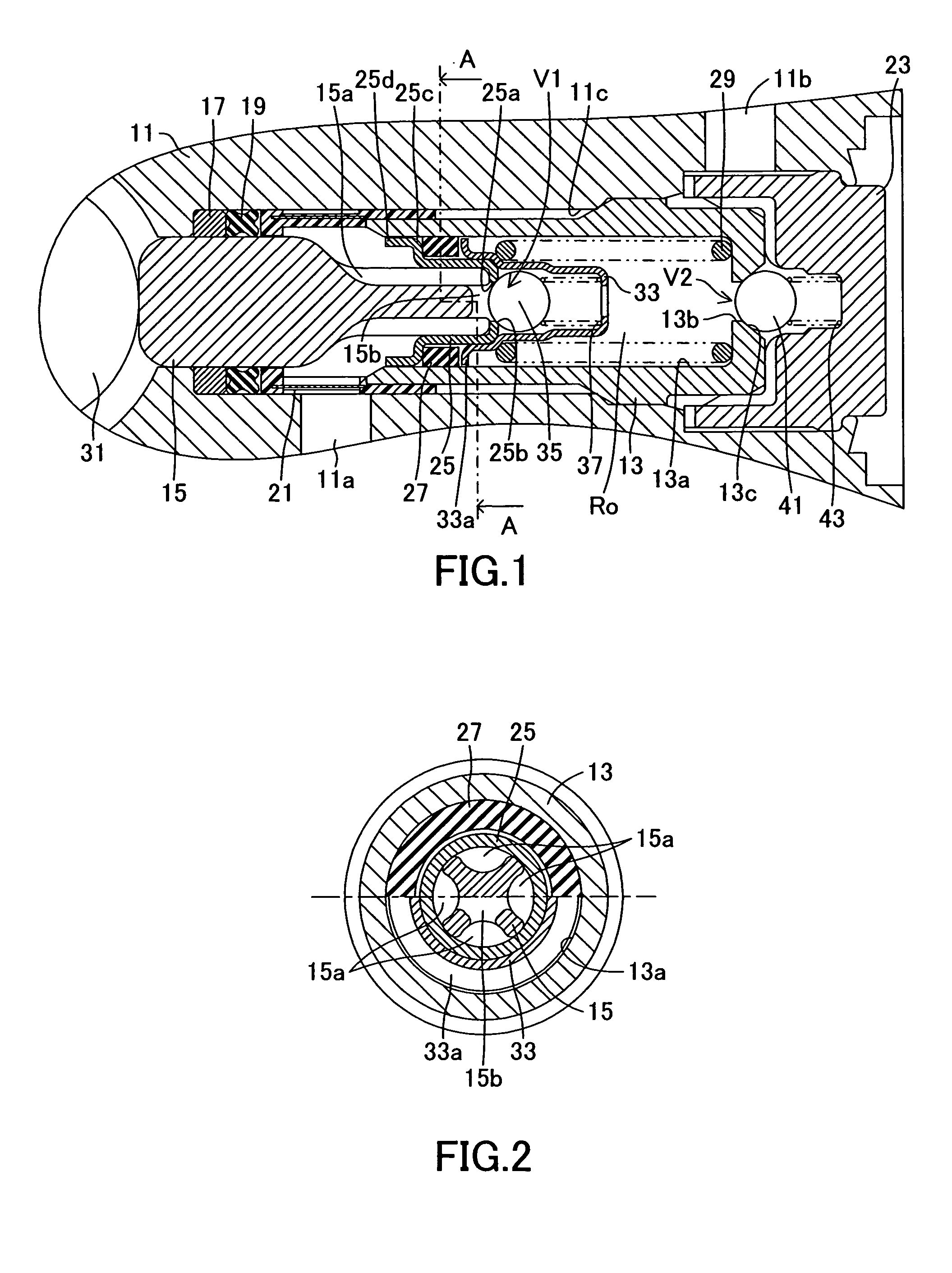
[0031] In the thus-configured piston pump of the first embodiment, when an electric motor (not shown) rotates the eccentric member 31, the eccentric member 31 and the piston return spring 29 cooperatively function to axially reciprocate the piston 15, thereby alternately increasing and decreasing the volume of the pump chamber Ro. The suction valve V1 and the discharge valve V2 function accordingly, whereby fluid flows from the suction port 11a to the discharge port 11b.

[0032] In the piston pump of the first embodiment, a portion of the flow path connecting the suction port 11a and the suction valve V1 is defined by the plurality of communicating grooves 15a formed on the outer circumferential surface of the piston 15, and the cylindrical seat member 25 externally and fixedly fitted to the piston 15 in a region corresponding to the communicating grooves 15a. This feature allows the piston 15 to be manufactured without involvement of cuffing (the piston 15 can be, for example, a for...

fourth embodiment

[0040] In the fourth embodiment shown in FIG. 5, the filter 21 is provided in a region other than the piston pump. An annular mounting groove 25f is formed on the seat member 25. A slide ring 39 is fitted into the annular mounting groove 25f in an axially movable condition. Radially extending communication holes 25g are formed in the seat member 25 in order to establish communication between a bottom portion of the annular mounting groove 25f and the corresponding communicating grooves 15a. The slide ring 39 can move along the axial direction of the piston 15 in relation to the piston 15 while synchronizing with increase and decrease in the volume of the pump chamber Ro. The slide ring 39 serves as a partition between a suction chamber R1 and a discharge chamber R2, which are provided between the pump housing 11 and the piston 15.

[0041] In the fourth embodiment, when the volume of the pump chamber Ro increases, the slide ring 39 shuts off communication between the suction chamber R1...


PUM


Abstract

A piston pump includes a piston for increasing and decreasing the volume of a pump chamber formed in a cylinder bore of a cylinder member, by means of axially reciprocating movement thereof; a suction valve provided in the piston, and opening and closing when the volume of the pump chamber increases and decreases, respectively; and a discharge valve provided at a discharge side of the pump chamber, and opening and closing when the volume of the pump chamber decreases and increases, respectively. A plurality of mutually communicating, axially extending grooves are formed on an outer circumferential portion of the piston located on the pump-chamber side. A cylindrical seat member is fixedly and externally fitted to the piston in a region of the communicating grooves. A valve port and a valve seat of the suction valve are formed at an end portion of the seat member located on the pump-chamber side.

Description

BACKGROUND OF THE INVENTION [0001] 1. Field of the Invention [0002] The present invention relates to a piston pump for use in, for example, a vehicular brake apparatus. [0003] 2. Description of the Related Art [0004] Piston pumps of such a type are disclosed in, for example, Japanese kohyo (PCT) Patent Publication No. 2001-501273 and Japanese Patent No. 3278982. Each of the disclosed piston pumps includes a pump housing having a cylinder bore formed therein; a piston which defines a pump chamber within the cylinder bore and is axially reciprocated so as to increase and decrease the volume of the pump chamber; a suction valve provided in the piston, opening when the volume of the pump chamber increases, and closing when the volume decreases; and a discharge valve provided at the discharge side of the pump chamber, opening when the volume of the pump chamber decreases, and closing when the volume increases. The piston is axially reciprocated to thereby increase and decrease the volume...

Claims


Application Information

Patent Timeline
IPC IPC(8): B60T8/40F04B1/04F04B53/12F04B53/14
CPCB60T8/4031F04B1/0452F04B1/0408
Inventor MAEDA, JUNICHI
Owner ADVICS CO LTD
Why Eureka
Try Eureka